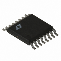
LT3837EFE#TRPBF Linear Technology, LT3837EFE#TRPBF Datasheet - Page 20

LT3837EFE#TRPBF
Manufacturer Part Number
LT3837EFE#TRPBF
Description
IC CNTRLR SYNC ISO 16TSSOP
Manufacturer
Linear Technology
Type
Flybackr
Datasheet
1.LT3837EFETRPBF.pdf
(28 pages)
Specifications of LT3837EFE#TRPBF
Internal Switch(s)
No
Synchronous Rectifier
Yes
Number Of Outputs
1
Frequency - Switching
50kHz ~ 250kHz
Voltage - Input
4.5 ~ 20 V
Operating Temperature
-40°C ~ 125°C
Mounting Type
Surface Mount
Package / Case
16-TSSOP Exposed Pad, 16-eTSSOP, 16-HTSSOP
Lead Free Status / RoHS Status
Lead free / RoHS Compliant
Current - Output
-
Voltage - Output
-
Power - Output
-
Available stocks
Company
Part Number
Manufacturer
Quantity
Price
APPLICATIONS INFORMATION
LT3837
Minimum Load Considerations
At light loads, the LT3837 derived regulator goes into
forced continuous conduction mode. The primary side
switch always turns on for a short time as set by the
t
load requires, power will fl ow back into the primary during
the “off” period when the synchronization switch is on.
This does not produce any inherently adverse problems,
though light load effi ciency is reduced.
Maximum Load Considerations
The current mode control uses the V
amplifi ed sense resistor voltage as inputs to the current
comparator. When the amplifi ed sense voltage exceeds the
V
In normal use, the peak switch current increases while
FB is below the internal reference. This continues until
V
MOSFET will turn off at the rated 98mV V
repeats on the next cycle.
It is possible for the peak primary switch currents as
referred across R
because of the minimum switch-on time blanking. If the
voltage on V
turn-on time, the SFST capacitor is discharged, which also
discharges the V
current on the next cycle and will reduce overall stress in
the primary switch.
Short-Circuit Conditions
Loss of current limit is possible under certain conditions
such as an output short-circuit. If the duty cycle exhib-
ited by the minimum on-time is greater than the ratio of
secondary winding voltage (referred-to-primary) divided
by input voltage, then peak current is not controlled at
the nominal value. It ratchets up cycle-by-cycle to some
20
ON(MIN)
C
C
node voltage, the primary side switch is turned off.
reaches its 2.56V clamp. At clamp, the primary side
resistor. If this produces more power than the
SENSE
C
SENSE
capacitor. This then reduces the peak
reaches 206mV after the minimum
to exceed the max 98mV rating
C
node voltage and
SENSE
level. This
higher level. Expressed mathematically, the requirement
to maintain short-circuit control is:
where:
Other variables as previously defi ned.
Trouble is typically encountered only in applications with a
relatively high product of input voltage times secondary-
to-primary turns ratio and/or a relatively long minimum
switch-on time. Additionally, several real world effects such
as transformer leakage inductance, AC winding losses, and
output switch voltage drop combine to make this simple
theoretical calculation a conservative estimate. Prudent
design evaluates the switcher for short-circuit protection
and adds any additional circuitry to prevent destruction.
Output Voltage Error Sources
The LT3837’s feedback sensing introduces additional
sources of errors. The following is a summary list.
The internal bandgap voltage reference sets the reference
voltage for the feedback amplifi er. The specifi cations detail
its variation.
The external feedback resistive divider ratio proportional
directly affects regulated voltage. Use 1% components.
Leakage inductance on the transformer secondary reduces
the effective secondary-to-feedback winding turns ratio
(N
age target by a similar percentage. Since secondary leakage
inductance is constant from part to part (with a tolerance)
adjust the feedback resistor ratio to compensate.
The transformer secondary current fl ows through the im-
pedances of the winding resistance, synchronous MOSFET
R
current for these errors is higher than the load current
because conduction occurs only during the converter’s
“off” time. So divide the load current by (1 – DC).
DS(ON)
S
t
I
DC
ON(MIN)
SC
/N
F
MIN
= short-circuit output current
) from its ideal value. This increases the output volt-
and output capacitor ESR. The DC equivalent
=
= primary side switch minimum on-time
t
ON MIN
(
)
•
f
OSC
<
I
SC
•
(
R
V
SEC
IN
•
+
N
S S P
R
DS ON
(
)
)
3837fc


