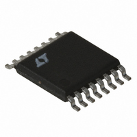
LT3837EFE#TRPBF Linear Technology, LT3837EFE#TRPBF Datasheet - Page 17

LT3837EFE#TRPBF
Manufacturer Part Number
LT3837EFE#TRPBF
Description
IC CNTRLR SYNC ISO 16TSSOP
Manufacturer
Linear Technology
Type
Flybackr
Datasheet
1.LT3837EFETRPBF.pdf
(28 pages)
Specifications of LT3837EFE#TRPBF
Internal Switch(s)
No
Synchronous Rectifier
Yes
Number Of Outputs
1
Frequency - Switching
50kHz ~ 250kHz
Voltage - Input
4.5 ~ 20 V
Operating Temperature
-40°C ~ 125°C
Mounting Type
Surface Mount
Package / Case
16-TSSOP Exposed Pad, 16-eTSSOP, 16-HTSSOP
Lead Free Status / RoHS Status
Lead free / RoHS Compliant
Current - Output
-
Voltage - Output
-
Power - Output
-
Available stocks
Company
Part Number
Manufacturer
Quantity
Price
APPLICATIONS INFORMATION
5. Verify this result by connecting a resistor of this value
6. Disconnect the ground short to C
Setting Frequency
The switching frequency of the LT3837 is set by an
external capacitor connected between the OSC pin and
ground. Recommended values are between 200pF and
33pF, yielding switching frequencies between 50kHz and
250kHz. Figure 3 shows the nominal relationship between
external capacitance and switching frequency. Place the
capacitor as close as possible to the IC and minimize OSC
trace length and area to minimize stray capacitance and
potential noise pickup.
from the R
requisite 0.1μF fi lter capacitor to ground. Measure
the output impedance R
new compensation in place. R
decreased signifi cantly. Fine tuning is accomplished
experimentally by slightly altering R
estimate for R
where R′
resistor, R
in place and R
load compensation (from step 2).
R
′
CMP
=
300
200
100
50
R
CMP
Figure 3. f
CMP
S(OUT)CMP
CMP
is the new value for the load compensation
30
CMP
S(OUT)
•
pin to ground.
⎛
⎜
⎝
1
OSC
is:
+
is the output impedance with R
R
is the output impedance with no
vs OSC Capacitor Values
C
S OUT CMP
OSCAP
R
(
S(OUT)
S OUT
(
(pF)
)
100
)
= ΔV
⎞
⎟
⎠
CMP
S(OUT)
OUT
3837 F03
and connect the
CMP
/ΔI
200
should have
OUT
. A revised
with the
CMP
You can synchronize the oscillator frequency to an external
frequency. This is done with a signal on the SYNC pin. Set
the LT3837 frequency 10% slower than the desired external
frequency using the OSC pin capacitor, then use a pulse
on the SYNC pin of amplitude greater than 2V and with the
desired period. The rising edge of the SYNC signal initiates
an OSC capacitor discharge forcing primary MOSFET off
(PG voltage goes low). If the oscillator frequency is much
different from the sync frequency, problems may occur
with slope compensation and system stability. Keep the
sync pulse width greater than 500ns.
Selecting Timing Resistors
There are three internal “one-shot” times that are pro-
grammed by external application resistors: minimum
on-time, enable delay time and primary MOSFET turn-on
delay. These are all part of the isolated fl yback control
technique, and their functions are previously outlined in
the Theory of Operation section.
The following information should help in selecting and/or
optimizing these timing values.
Minimum On-Time (t
Minimum on-time is the programmable period during
which current limit is blanked (ignored) after the turn
on of the primary side switch. This improves regulator
performance by eliminating false tripping on the leading
edge spike in the switch, especially at light loads. This
spike is due to both the gate/source charging current and
the discharge of drain capacitance. The isolated fl yback
sensing requires a pulse to sense the output. Minimum
on-time ensures that there is always a signal to close the
feedback loop. The LT3837 does not employ cycle skipping
at light loads. Therefore, minimum on-time along with
synchronous rectifi cation sets the switch over in forced
continuous mode operation.
The t
Keep R
is 160k.
R
tON MIN
ON(MIN)
tON(MIN)
(
)
(
resistor is set with the following equation:
k
Ω =
greater than 70k. A good starting value
)
t
ON MIN
ON(MIN)
(
1 063
)
.
( ) –
ns
)
104
LT3837
17
3837fc


