PCM18XK1 Microchip Technology, PCM18XK1 Datasheet - Page 261
PCM18XK1
Manufacturer Part Number
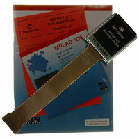
PCM18XK1
Description
MODULE PROC PIC18F8680,6680,8565
Manufacturer
Microchip Technology
Datasheet
1.PCM18XK1.pdf
(496 pages)
Specifications of PCM18XK1
Accessory Type
Processor Module
Lead Free Status / RoHS Status
Not applicable / Not applicable
For Use With/related Products
ICE2000
For Use With
ICE2000 - EMULATOR MPLAB-ICE 2000 POD
Lead Free Status / Rohs Status
Lead free / RoHS Compliant


20.0
The
comparators. The inputs to the comparators are
multiplexed with the RF1 through RF6 pins. The on-
chip voltage reference (Section 21.0 “Comparator
Voltage Reference Module”) can also be an input to
the comparators.
REGISTER 20-1:
2004 Microchip Technology Inc.
comparator
COMPARATOR MODULE
bit 7
bit 6
bit 5
bit 4
bit 3
bit 2-0
module
CMCON REGISTER
C2OUT: Comparator 2 Output bit
When C2INV = 0:
1 = C2 V
0 = C2 V
When C2INV = 1:
1 = C2 V
0 = C2 V
C1OUT: Comparator 1 Output bit
When C1INV = 0:
1 = C1 V
0 = C1 V
When C1INV = 1:
1 = C1 V
0 = C1 V
C2INV: Comparator 2 Output Inversion bit
1 = C2 output inverted
0 = C2 output not inverted
C1INV: Comparator 1 Output Inversion bit
1 = C1 output inverted
0 = C1 output not inverted
CIS: Comparator Input Switch bit
When CM2:CM0 = 110:
1 = C1 V
0 = C1 V
CM2:CM0: Comparator Mode bits
Figure 20-1 shows the Comparator modes and CM2:CM0 bit settings.
Legend:
R = Readable bit
- n = Value at POR
bit 7
C2OUT
R-0
C2 V
C2 V
contains
IN
IN
IN
IN
IN
IN
IN
IN
IN
IN
IN
IN
+ > C2 V
+ < C2 V
+ < C2 V
+ > C2 V
+ > C1 V
+ < C1 V
+ < C1 V
+ > C1 V
- connects to RF5/AN10
- connects to RF3/AN8
- connects to RF6/AN11
- connects to RF4/AN9
C1OUT
R-0
two
IN
IN
IN
IN
IN
IN
IN
IN
-
-
-
-
-
-
-
-
PIC18F6585/8585/6680/8680
analog
C2INV
R/W-0
W = Writable bit
‘1’ = Bit is set
C1INV
R/W-0
The CMCON register, shown in Register 20-1, controls
the comparator input and output multiplexers. A block
diagram of the various comparator configurations is
shown in Figure 20-1.
R/W-0
U = Unimplemented bit, read as ‘0’
‘0’ = Bit is cleared
CIS
R/W-0
CM2
x = Bit is unknown
R/W-0
CM1
DS30491C-page 259
R/W-0
CM0
bit 0
Related parts for PCM18XK1
Image
Part Number
Description
Manufacturer
Datasheet
Request
R

Part Number:
Description:
Manufacturer:
Microchip Technology Inc.
Datasheet:
Part Number:
Description:
Manufacturer:
Microchip Technology Inc.
Datasheet:
Part Number:
Description:
Manufacturer:
Microchip Technology Inc.
Datasheet:
Part Number:
Description:
Manufacturer:
Microchip Technology Inc.
Datasheet:
Part Number:
Description:
Manufacturer:
Microchip Technology Inc.
Datasheet:
Part Number:
Description:
Manufacturer:
Microchip Technology Inc.
Datasheet:
Part Number:
Description:
Manufacturer:
Microchip Technology Inc.
Datasheet:
Part Number:
Description:
Manufacturer:
Microchip Technology Inc.
Datasheet: