PCM18XK1 Microchip Technology, PCM18XK1 Datasheet - Page 271
PCM18XK1
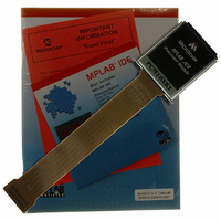
Manufacturer Part Number
PCM18XK1
Description
MODULE PROC PIC18F8680,6680,8565
Manufacturer
Microchip Technology
Datasheet
1.PCM18XK1.pdf
(496 pages)
Specifications of PCM18XK1
Accessory Type
Processor Module
Lead Free Status / RoHS Status
Not applicable / Not applicable
For Use With/related Products
ICE2000
For Use With
ICE2000 - EMULATOR MPLAB-ICE 2000 POD
Lead Free Status / Rohs Status
Lead free / RoHS Compliant


22.0
In many applications, the ability to determine if the
device voltage (V
is a desirable feature. A window of operation for the
application can be created where the application soft-
ware can do “housekeeping tasks” before the device
voltage exits the valid operating range. This can be
done using the Low-Voltage Detect module.
This module is a software programmable circuitry
where a device voltage trip point can be specified.
When the voltage of the device becomes lower then the
specified point, an interrupt flag is set. If the interrupt is
enabled, the program execution will branch to the inter-
rupt vector address and the software can then respond
to that interrupt source.
FIGURE 22-1:
The block diagram for the LVD module is shown in
Figure 22-2. A comparator uses an internally gener-
ated reference voltage as the set point. When the
selected tap output of the device voltage crosses the
set point (is lower than), the LVDIF bit is set.
Each node in the resistor divider represents a “trip
point” voltage. The “trip point” voltage is the minimum
supply voltage level at which the device can operate
before the LVD module asserts an interrupt. When the
2004 Microchip Technology Inc.
LOW-VOLTAGE DETECT
DD
V
V
) is below a specified voltage level
A
B
TYPICAL LOW-VOLTAGE DETECT APPLICATION
Time
PIC18F6585/8585/6680/8680
T
A
T
B
The Low-Voltage Detect circuitry is completely under
software control. This allows the circuitry to be “turned
off” by the software which minimizes the current
consumption for the device.
Figure 22-1 shows a possible application voltage curve
(typically for batteries). Over time, the device voltage
decreases. When the device voltage equals voltage V
the LVD logic generates an interrupt. This occurs at
time T
until the device voltage is no longer in valid operating
range, to shut down the system. Voltage point V
minimum valid operating voltage specification. This
occurs at time T
time for shutdown.
supply voltage is equal to the trip point, the voltage
tapped off of the resistor array is equal to the 1.2V
internal reference voltage generated by the voltage
reference module. The comparator then generates an
interrupt signal setting the LVDIF bit. This voltage is
software programmable to any one of 16 values (see
Figure 22-2).
programming the LVDL3:LVDL0 bits (LVDCON<3:0>).
A
. The application software then has the time,
Legend:
V
V
A
B
= LVD trip point
= Minimum valid device
The
B
operating voltage
. The difference, T
trip
point
DS30491C-page 269
B
is
– T
selected
A
, is the total
B
is the
by
A
,
Related parts for PCM18XK1
Image
Part Number
Description
Manufacturer
Datasheet
Request
R

Part Number:
Description:
Manufacturer:
Microchip Technology Inc.
Datasheet:
Part Number:
Description:
Manufacturer:
Microchip Technology Inc.
Datasheet:
Part Number:
Description:
Manufacturer:
Microchip Technology Inc.
Datasheet:
Part Number:
Description:
Manufacturer:
Microchip Technology Inc.
Datasheet:
Part Number:
Description:
Manufacturer:
Microchip Technology Inc.
Datasheet:
Part Number:
Description:
Manufacturer:
Microchip Technology Inc.
Datasheet:
Part Number:
Description:
Manufacturer:
Microchip Technology Inc.
Datasheet:
Part Number:
Description:
Manufacturer:
Microchip Technology Inc.
Datasheet: