PCM18XK1 Microchip Technology, PCM18XK1 Datasheet - Page 282
PCM18XK1
Manufacturer Part Number
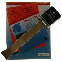
PCM18XK1
Description
MODULE PROC PIC18F8680,6680,8565
Manufacturer
Microchip Technology
Datasheet
1.PCM18XK1.pdf
(496 pages)
Specifications of PCM18XK1
Accessory Type
Processor Module
Lead Free Status / RoHS Status
Not applicable / Not applicable
For Use With/related Products
ICE2000
For Use With
ICE2000 - EMULATOR MPLAB-ICE 2000 POD
Lead Free Status / Rohs Status
Lead free / RoHS Compliant


PIC18F6585/8585/6680/8680
REGISTER 23-2:
DS30491C-page 280
bit 4-0
CANSTAT: CAN STATUS REGISTER (CONTINUED)
Legend:
C = Clearable bit
‘1’ = Bit is set
Mode 1,2:
EICODE4:EICODE0: Interrupt Code bits in Mode 1 and Mode 2
When an interrupt occurs, a prioritized coded interrupt value will be present in these bits. This
code indicates the source of the interrupt. Unlike ICODE bits in Mode 0, these bits may not be
copied directly to EWIN bits to map interrupted buffer to Access Bank area. If required, user
software may maintain a table in program memory to map EICODE bits to EWIN bits and access
interrupt buffer in Access Bank area.
No interrupt
Error interrupt
TXB2 interrupt
TXB1 interrupt
TXB0 interrupt
RXB1 interrupt
RXB0 interrupt
Wake-up interrupt
RX/TX B0 interrupt
RX/TX B1 interrupt
RX/TX B2 interrupt
RX/TX B3 interrupt
RX/TX B4 interrupt
RX/TX B4 interrupt
Note 1: To achieve maximum power saving and/or able to wake-up on CAN bus activity,
2: In Mode 2, if the buffer is configured as a receiver, EICODE bits will always contain
switch CAN module to Disable mode before putting the device to Sleep.
‘10000’ upon interrupt.
U = Unimplemented bit, read as ‘0’
R = Readable bit
‘0’ = Bit is cleared
EICODE4:EICODE0 Value
10001/10000
10010
10011
10100
10101
10110
10111
00000
00010
00100
00110
01000
10000
01110
(2)
(2)
(2)
(2)
(2)
(2)
W = Writable bit
(2)
- n = Value at POR
x = Bit is unknown
2004 Microchip Technology Inc.
Related parts for PCM18XK1
Image
Part Number
Description
Manufacturer
Datasheet
Request
R

Part Number:
Description:
Manufacturer:
Microchip Technology Inc.
Datasheet:
Part Number:
Description:
Manufacturer:
Microchip Technology Inc.
Datasheet:
Part Number:
Description:
Manufacturer:
Microchip Technology Inc.
Datasheet:
Part Number:
Description:
Manufacturer:
Microchip Technology Inc.
Datasheet:
Part Number:
Description:
Manufacturer:
Microchip Technology Inc.
Datasheet:
Part Number:
Description:
Manufacturer:
Microchip Technology Inc.
Datasheet:
Part Number:
Description:
Manufacturer:
Microchip Technology Inc.
Datasheet:
Part Number:
Description:
Manufacturer:
Microchip Technology Inc.
Datasheet: