ATEVK1105 Atmel, ATEVK1105 Datasheet - Page 151
ATEVK1105
Manufacturer Part Number
ATEVK1105
Description
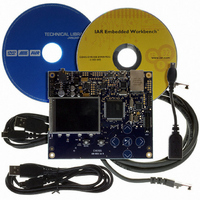
KIT EVAL FOR AT32UC3A0
Manufacturer
Atmel
Series
AVR®32r
Type
MCUr
Datasheets
1.ATAVRONE-PROBECBL.pdf
(16 pages)
2.ATEVK1104.pdf
(826 pages)
3.ATEVK1105.pdf
(28 pages)
Specifications of ATEVK1105
Contents
Evaluation Board, Software and Documentation
Processor To Be Evaluated
AT32UC3A0512
Processor Series
AVR
Data Bus Width
32 bit
Interface Type
USART, TWI, USB, SPI, Ethernet
Operating Supply Voltage
3.3 V
Silicon Manufacturer
Atmel
Core Architecture
AVR
Core Sub-architecture
AVR UC3
Silicon Core Number
AT32UC3A0512
Silicon Family Name
AVR
Kit Contents
Board CD Docs
Rohs Compliant
Yes
For Use With/related Products
AT32UC3A0
Lead Free Status / RoHS Status
Lead free / RoHS Compliant


20.6
20.6.1
20.6.2
20.6.3
20.7
20.7.1
20.7.2
32058J–AVR32–04/11
Product Dependencies
Functional Description
I/O Lines
Power Management
Interrupt
Bus Multiplexing
Pull-up Control
The pins used for interfacing the External Bus Interface may be multiplexed with the GPIO lines.
The programmer must first program the GPIO controller to assign the External Bus Interface
pins to their peripheral function. If I/O lines of the External Bus Interface are not used by the
application, they can be used for other purposes by the GPIO Controller.
The EBI HSB clock and SDRAMC, SMC and ECC PB clocks are generated by the Power Man-
ager. Before using the EBI, the programmer must ensure that these clocks are enabled in the
Power Manager.
To prevent bus errors EBI operation must be terminated before entering sleep mode
The EBI interface has an interrupt line connected to the Interrupt Controller. Handling the EBI
interrupt requires programming the interrupt controller before configuring the EBI.
The EBI transfers data between the internal HSB Bus (handled by the HMatrix) and the external
memories or peripheral devices. It controls the waveforms and the parameters of the external
address, data and control busses and is composed of the following elements:
• The Static Memory Controller (SMC)
• The SDRAM Controller (SDRAMC)
• A chip select assignment feature that assigns an HSB address space to the external devices
• A multiplex controller circuit that shares the pins between the different Memory Controllers
The EBI offers a complete set of control signals that share the 16-bit data lines, the address
lines of up to 24 bits and the control signals through a multiplex logic operating in function of the
memory area requests.
Multiplexing is specifically organized in order to guarantee the maintenance of the address and
output control lines at a stable state while no external access is being performed. Multiplexing is
also designed to respect the data float times defined in the Memory Controllers. Furthermore,
refresh cycles of the SDRAM are executed independently by the SDRAM Controller without
delaying the other external Memory Controller accesses.
A specific HMATRIX_SFR register in the Matrix User Interface permit enabling of on-chip pull-up
resistors on the data bus lines not multiplexed with the GPIO Controller lines. For details on this
register, refer to the Peripherals Section. The pull-up resistors are enabled after reset. Setting
the EBI_DBPUC bit disables the pull-up resistors on lines not muxed with GPIO. Enabling the
pull-up resistor on lines multiplexed with GPIO lines can be performed by programming the
appropriate GPIO controller.
AT32UC3A
151
Related parts for ATEVK1105
Image
Part Number
Description
Manufacturer
Datasheet
Request
R

Part Number:
Description:
DEV KIT FOR AVR/AVR32
Manufacturer:
Atmel
Datasheet:

Part Number:
Description:
INTERVAL AND WIPE/WASH WIPER CONTROL IC WITH DELAY
Manufacturer:
ATMEL Corporation
Datasheet:
Part Number:
Description:
Low-Voltage Voice-Switched IC for Hands-Free Operation
Manufacturer:
ATMEL Corporation
Datasheet:
Part Number:
Description:
MONOLITHIC INTEGRATED FEATUREPHONE CIRCUIT
Manufacturer:
ATMEL Corporation
Datasheet:
Part Number:
Description:
AM-FM Receiver IC U4255BM-M
Manufacturer:
ATMEL Corporation
Datasheet:
Part Number:
Description:
Monolithic Integrated Feature Phone Circuit
Manufacturer:
ATMEL Corporation
Datasheet:
Part Number:
Description:
Multistandard Video-IF and Quasi Parallel Sound Processing
Manufacturer:
ATMEL Corporation
Datasheet:
Part Number:
Description:
High-performance EE PLD
Manufacturer:
ATMEL Corporation
Datasheet:
Part Number:
Description:
8-bit Flash Microcontroller
Manufacturer:
ATMEL Corporation
Datasheet:
Part Number:
Description:
2-Wire Serial EEPROM
Manufacturer:
ATMEL Corporation
Datasheet: