ATEVK1105 Atmel, ATEVK1105 Datasheet - Page 415
ATEVK1105
Manufacturer Part Number
ATEVK1105
Description
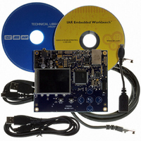
KIT EVAL FOR AT32UC3A0
Manufacturer
Atmel
Series
AVR®32r
Type
MCUr
Datasheets
1.ATAVRONE-PROBECBL.pdf
(16 pages)
2.ATEVK1104.pdf
(826 pages)
3.ATEVK1105.pdf
(28 pages)
Specifications of ATEVK1105
Contents
Evaluation Board, Software and Documentation
Processor To Be Evaluated
AT32UC3A0512
Processor Series
AVR
Data Bus Width
32 bit
Interface Type
USART, TWI, USB, SPI, Ethernet
Operating Supply Voltage
3.3 V
Silicon Manufacturer
Atmel
Core Architecture
AVR
Core Sub-architecture
AVR UC3
Silicon Core Number
AT32UC3A0512
Silicon Family Name
AVR
Kit Contents
Board CD Docs
Rohs Compliant
Yes
For Use With/related Products
AT32UC3A0
Lead Free Status / RoHS Status
Lead free / RoHS Compliant


28.6
28.6.1
32058J–AVR32–04/11
Product Dependencies
SDRAM Device Initialization
The initialization sequence is generated by software. The SDRAM devices are initialized by the
following sequence:
1. SDRAM features must be set in the configuration register: asynchronous timings (TRC,
2. For mobile SDRAM, temperature-compensated self refresh (TCSR), drive strength (DS)
3. The SDRAM memory type must be set in the Memory Device Register.
4. An No Operation (NOP)command must be issued to the SDRAM devices to start the
5. A minimum pause of 200 µs is provided to precede any signal toggle.
6. An All Banks Precharge command must be issued to the SDRAM devices. The applica-
7. Eight auto-refresh (CBR) cycles are provided. The application must set the Mode to 4 in
8. A Mode Register set (MRS) cycle must be issued to program the parameters of the
9. For mobile SDRAM initialization, an Extended Mode Register set (EMRS) cycle must be
10. The application must go into Normal Mode, setting Mode to 0 in the Mode Register and
11. Write the refresh rate into the count field in the SDRAMC Refresh Timer register.
After initialization, the SDRAM devices are fully functional.
TRAS, ...), number of column, rows, CAS latency, and the data bus width.
and partial array self refresh (PASR) must be set in the Low Power Register.
SDRAM clock. The application must set Mode to 1 in the and perform a write access to
any SDRAM address.
tion must set Mode to 2 in the Mode Register and perform a write access to any SDRAM
address.
the Mode Register and performs a write access to any SDRAM location eight times.
SDRAM devices, in particular CAS latency and burst length. The application must set
Mode to 3 in the Mode Register and perform a write access to the SDRAM. The write
address must be chosen so that BA[1:0] are set to 0. For example, with a 16-bit 128 MB
SDRAM (12 rows, 9 columns, 4 banks) bank address, the SDRAM write access should
be done at the address 0x20000000.
issued to program the SDRAM parameters (TCSR, PASR, DS). The application must set
Mode to 5 in the Mode Register and perform a write access to the SDRAM. The write
address must be chosen so that BA[1] or BA[0] are set to 1. For example, with a 16-bit
128 MB SDRAM, (12 rows, 9 columns, 4 banks) bank address the SDRAM write access
should be done at the address 0x20800000 or 0x20400000.
performing a write access at any location in the SDRAM.
(Refresh rate = delay between refresh cycles). The SDRAM device requires a refresh
every 15.625 us or 7.81 us. With a 100 MHz frequency, the Refresh Timer Counter Reg-
ister must be set with the value 1562 (15.625 µs x 100 MHz) or 781 (7.81 µs x 100 MHz).
AT32UC3A
415
Related parts for ATEVK1105
Image
Part Number
Description
Manufacturer
Datasheet
Request
R

Part Number:
Description:
DEV KIT FOR AVR/AVR32
Manufacturer:
Atmel
Datasheet:

Part Number:
Description:
INTERVAL AND WIPE/WASH WIPER CONTROL IC WITH DELAY
Manufacturer:
ATMEL Corporation
Datasheet:
Part Number:
Description:
Low-Voltage Voice-Switched IC for Hands-Free Operation
Manufacturer:
ATMEL Corporation
Datasheet:
Part Number:
Description:
MONOLITHIC INTEGRATED FEATUREPHONE CIRCUIT
Manufacturer:
ATMEL Corporation
Datasheet:
Part Number:
Description:
AM-FM Receiver IC U4255BM-M
Manufacturer:
ATMEL Corporation
Datasheet:
Part Number:
Description:
Monolithic Integrated Feature Phone Circuit
Manufacturer:
ATMEL Corporation
Datasheet:
Part Number:
Description:
Multistandard Video-IF and Quasi Parallel Sound Processing
Manufacturer:
ATMEL Corporation
Datasheet:
Part Number:
Description:
High-performance EE PLD
Manufacturer:
ATMEL Corporation
Datasheet:
Part Number:
Description:
8-bit Flash Microcontroller
Manufacturer:
ATMEL Corporation
Datasheet:
Part Number:
Description:
2-Wire Serial EEPROM
Manufacturer:
ATMEL Corporation
Datasheet: