ATEVK1105 Atmel, ATEVK1105 Datasheet - Page 326
ATEVK1105
Manufacturer Part Number
ATEVK1105
Description
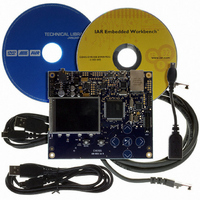
KIT EVAL FOR AT32UC3A0
Manufacturer
Atmel
Series
AVR®32r
Type
MCUr
Datasheets
1.ATAVRONE-PROBECBL.pdf
(16 pages)
2.ATEVK1104.pdf
(826 pages)
3.ATEVK1105.pdf
(28 pages)
Specifications of ATEVK1105
Contents
Evaluation Board, Software and Documentation
Processor To Be Evaluated
AT32UC3A0512
Processor Series
AVR
Data Bus Width
32 bit
Interface Type
USART, TWI, USB, SPI, Ethernet
Operating Supply Voltage
3.3 V
Silicon Manufacturer
Atmel
Core Architecture
AVR
Core Sub-architecture
AVR UC3
Silicon Core Number
AT32UC3A0512
Silicon Family Name
AVR
Kit Contents
Board CD Docs
Rohs Compliant
Yes
For Use With/related Products
AT32UC3A0
Lead Free Status / RoHS Status
Lead free / RoHS Compliant


Figure 26-28. Receiver Behavior when Operating with Hardware Handshaking
26.7.5
26.7.5.1
32058J–AVR32–04/11
RXBUFF
US_CR
Write
RXD
RTS
ISO7816 Mode
RXEN = 1
ISO7816 Mode Overview
Setting the USART to operate with hardware handshaking is performed by writing the MODE
field in the Mode Register (MR) to the value 0x2.
The USART behavior when hardware handshaking is enabled is the same as the behavior in
standard synchronous or asynchronous mode, except that the receiver drives the RTS pin as
described below and the level on the CTS pin modifies the behavior of the transmitter as
described below. Using this mode requires using the PDC channel for reception. The transmitter
can handle hardware handshaking in any case.
Figure 26-28 on page 326
The RTS pin is driven high if the receiver is disabled and if the status RXBUFF (Receive Buffer
Full) coming from the PDC channel is high. Normally, the remote device does not start transmit-
ting while its CTS pin (driven by RTS) is high. As soon as the Receiver is enabled, the RTS falls,
indicating to the remote device that it can start transmitting. Defining a new buffer to the PDC
clears the status bit RXBUFF and, as a result, asserts the pin RTS low.
Figure 26-29 on page 326
enabled. The CTS pin disables the transmitter. If a character is being processing, the transmitter
is disabled only after the completion of the current character and transmission of the next char-
acter happens as soon as the pin CTS falls.
Figure 26-29. Transmitter Behavior when Operating with Hardware Handshaking
The USART features an ISO7816-compatible operating mode. This mode permits interfacing
with smart cards and Security Access Modules (SAM) communicating through an ISO7816 link.
Both T = 0 and T = 1 protocols defined by the ISO7816 specification are supported.
Setting the USART in ISO7816 mode is performed by writing the MODE field in the Mode Regis-
ter (MR) to the value 0x4 for protocol T = 0 and to the value 0x5 for protocol T = 1.
The ISO7816 is a half duplex communication on only one bidirectional line. The baud rate is
determined by a division of the clock provided to the remote device (see
on page
The USART connects to a smart card as shown in
becomes bidirectional and the Baud Rate Generator feeds the ISO7816 clock on the CLK pin.
305).
CTS
TXD
shows how the receiver operates if hardware handshaking is enabled.
shows how the transmitter operates if hardware handshaking is
Figure 26-30 on page
RXDIS = 1
”Baud Rate Generator”
AT32UC3A
327. The TXD line
326
Related parts for ATEVK1105
Image
Part Number
Description
Manufacturer
Datasheet
Request
R

Part Number:
Description:
DEV KIT FOR AVR/AVR32
Manufacturer:
Atmel
Datasheet:

Part Number:
Description:
INTERVAL AND WIPE/WASH WIPER CONTROL IC WITH DELAY
Manufacturer:
ATMEL Corporation
Datasheet:
Part Number:
Description:
Low-Voltage Voice-Switched IC for Hands-Free Operation
Manufacturer:
ATMEL Corporation
Datasheet:
Part Number:
Description:
MONOLITHIC INTEGRATED FEATUREPHONE CIRCUIT
Manufacturer:
ATMEL Corporation
Datasheet:
Part Number:
Description:
AM-FM Receiver IC U4255BM-M
Manufacturer:
ATMEL Corporation
Datasheet:
Part Number:
Description:
Monolithic Integrated Feature Phone Circuit
Manufacturer:
ATMEL Corporation
Datasheet:
Part Number:
Description:
Multistandard Video-IF and Quasi Parallel Sound Processing
Manufacturer:
ATMEL Corporation
Datasheet:
Part Number:
Description:
High-performance EE PLD
Manufacturer:
ATMEL Corporation
Datasheet:
Part Number:
Description:
8-bit Flash Microcontroller
Manufacturer:
ATMEL Corporation
Datasheet:
Part Number:
Description:
2-Wire Serial EEPROM
Manufacturer:
ATMEL Corporation
Datasheet: