ATEVK1105 Atmel, ATEVK1105 Datasheet - Page 723
ATEVK1105
Manufacturer Part Number
ATEVK1105
Description
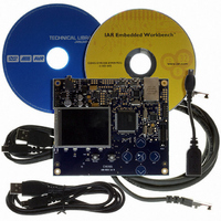
KIT EVAL FOR AT32UC3A0
Manufacturer
Atmel
Series
AVR®32r
Type
MCUr
Datasheets
1.ATAVRONE-PROBECBL.pdf
(16 pages)
2.ATEVK1104.pdf
(826 pages)
3.ATEVK1105.pdf
(28 pages)
Specifications of ATEVK1105
Contents
Evaluation Board, Software and Documentation
Processor To Be Evaluated
AT32UC3A0512
Processor Series
AVR
Data Bus Width
32 bit
Interface Type
USART, TWI, USB, SPI, Ethernet
Operating Supply Voltage
3.3 V
Silicon Manufacturer
Atmel
Core Architecture
AVR
Core Sub-architecture
AVR UC3
Silicon Core Number
AT32UC3A0512
Silicon Family Name
AVR
Kit Contents
Board CD Docs
Rohs Compliant
Yes
For Use With/related Products
AT32UC3A0
Lead Free Status / RoHS Status
Lead free / RoHS Compliant


34.5.3
34.5.4
34.5.5
34.6
34.6.1
32058J–AVR32–04/11
Functional Description
Clock Management
Interrupts
DMA
Equalization Filter
The Audio Bitstream DAC needs a separate clock for the D/A conversion operation. This clock
should be set up in the generic clock register in the power manager. The frequency of this clock
must be 256 times the frequency of the desired samplerate (f
clock must have a frequency of 12.288MHz.
The Audio Bitstream DAC interface has an interrupt line connected to the interrupt controller. In
order to handle interrupts, the interrupt controller must be programmed before configuring the
Audio Bitstream DAC.
All Audio Bitstream DAC interrupts can be enabled/disabled by writing to the Audio Bitstream
DAC Interrupt Enable/Disable Registers. Each pending and unmasked Audio Bitstream DAC
interrupt will assert the interrupt line. The Audio Bitstream DAC interrupt service routine can get
the interrupt source by reading the Interrupt Status Register.
The Audio Bitstream DAC is connected to the DMA controller. The DMA controller can be pro-
grammed to automatically transfer samples to the Audio Bitstream DAC Sample Data Register
(SDR) when the Audio Bitstream DAC is ready for new samples. This enables the Audio Bit-
stream DAC to operate without any CPU intervention such as polling the Interrupt Status
Register (ISR) or using interrupts. See the DMA controller documentation for details on how to
setup DMA transfers.
In order to use the Audio Bitstream DAC the product dependencies given in
page 722
and I/O lines in order to ensure correct operation of the Audio Bitstream DAC.
The Audio Bitstream DAC is enabled by writing the ENABLE bit in the Audio Bitstream DAC
Control Register (CR). The two 16-bit sample values for channel 0 and 1 can then be written to
the least and most significant halfword of the Sample Data Register (SDR), respectively. The
TX_READY bit in the Interrupt Status Register (ISR) will be set whenever the DAC is ready to
receive a new sample. A new sample value should be written to SDR before 256 DAC clock
cycles, or an underrun will occur, as indicated by the UNDERRUN status flags in ISR. ISR is
cleared when read, or when writing one to the corresponding bits in the Interrupt Clear Register
(ICR).
For interrupt-based operation, the relevant interrupts must be enabled by writing one to the cor-
responding bits in the Interrupt Enable Register (IER). Interrupts can be disabled by the Interrupt
Disable Register (IDR), and active interrupts are indicated in the read-only Interrupt Mask Regis-
ter (IMR).
The Audio Bitstream DAC can also be configured for peripheral DMA access, in which case only
the enable bit in the control register needs to be set in the Audio Bitstream DAC module.
The equalization filter is a simple 3-tap FIR filter. The purpose of this filter is to compensate for
the pass band frequency response of the sinc interpolation filter. The equalization filter makes
the pass band response more flat and moves the -3dB corner a little higher.
must be resolved. Particular attention should be given to the configuration of clocks
s
). For f
s
=48kHz this means that the
AT32UC3A
Section 34.5 on
723
Related parts for ATEVK1105
Image
Part Number
Description
Manufacturer
Datasheet
Request
R

Part Number:
Description:
DEV KIT FOR AVR/AVR32
Manufacturer:
Atmel
Datasheet:

Part Number:
Description:
INTERVAL AND WIPE/WASH WIPER CONTROL IC WITH DELAY
Manufacturer:
ATMEL Corporation
Datasheet:
Part Number:
Description:
Low-Voltage Voice-Switched IC for Hands-Free Operation
Manufacturer:
ATMEL Corporation
Datasheet:
Part Number:
Description:
MONOLITHIC INTEGRATED FEATUREPHONE CIRCUIT
Manufacturer:
ATMEL Corporation
Datasheet:
Part Number:
Description:
AM-FM Receiver IC U4255BM-M
Manufacturer:
ATMEL Corporation
Datasheet:
Part Number:
Description:
Monolithic Integrated Feature Phone Circuit
Manufacturer:
ATMEL Corporation
Datasheet:
Part Number:
Description:
Multistandard Video-IF and Quasi Parallel Sound Processing
Manufacturer:
ATMEL Corporation
Datasheet:
Part Number:
Description:
High-performance EE PLD
Manufacturer:
ATMEL Corporation
Datasheet:
Part Number:
Description:
8-bit Flash Microcontroller
Manufacturer:
ATMEL Corporation
Datasheet:
Part Number:
Description:
2-Wire Serial EEPROM
Manufacturer:
ATMEL Corporation
Datasheet: