ATEVK1105 Atmel, ATEVK1105 Datasheet - Page 60
ATEVK1105
Manufacturer Part Number
ATEVK1105
Description
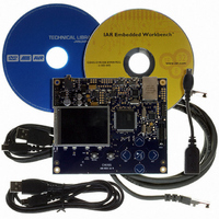
KIT EVAL FOR AT32UC3A0
Manufacturer
Atmel
Series
AVR®32r
Type
MCUr
Datasheets
1.ATAVRONE-PROBECBL.pdf
(16 pages)
2.ATEVK1104.pdf
(826 pages)
3.ATEVK1105.pdf
(28 pages)
Specifications of ATEVK1105
Contents
Evaluation Board, Software and Documentation
Processor To Be Evaluated
AT32UC3A0512
Processor Series
AVR
Data Bus Width
32 bit
Interface Type
USART, TWI, USB, SPI, Ethernet
Operating Supply Voltage
3.3 V
Silicon Manufacturer
Atmel
Core Architecture
AVR
Core Sub-architecture
AVR UC3
Silicon Core Number
AT32UC3A0512
Silicon Family Name
AVR
Kit Contents
Board CD Docs
Rohs Compliant
Yes
For Use With/related Products
AT32UC3A0
Lead Free Status / RoHS Status
Lead free / RoHS Compliant


13.5.7
13.5.7.1
13.5.7.2
Table 13-1.
32058J–AVR32–04/11
Index
0
1
2
3
4
5
Sleep modes
Sleep Mode
Idle
Frozen
Standby
Stop
DeepStop
Static
Entering and exiting sleep modes
Supported sleep modes
Sleep modes
In normal operation, all clock domains are active, allowing software execution and peripheral
operation. When the CPU is idle, it is possible to switch off the CPU clock and optionally other
clock domains to save power. This is activated by the sleep instruction, which takes the sleep
mode index number as argument.
The sleep instruction will halt the CPU and all modules belonging to the stopped clock domains.
The modules will be halted regardless of the bit settings of the mask registers.
Oscillators and PLLs can also be switched off to save power. Some of these modules have a rel-
atively long start-up time, and are only switched off when very low power consumption is
required.
The CPU and affected modules are restarted when the sleep mode is exited. This occurs when
an interrupt triggers. Note that even if an interrupt is enabled in sleep mode, it may not trigger if
the source module is not clocked.
The following sleep modes are supported. These are detailed in
•Idle: The CPU is stopped, the rest of the chip is operating. Wake-up sources are any interrupt.
•Frozen: The CPU and HSB modules are stopped, peripherals are operating. Wake-up sources
are any interrupt from PB modules.
•Standby: All synchronous clocks are stopped, but oscillators and PLLs are running, allowing
quick wake-up to normal mode. Wake-up sources are RTC or external interrupt (EIC).
•Stop: As Standby, but Oscillator 0 and 1, and the PLLs are stopped. 32 KHz (if enabled) and
RC oscillators and RTC/WDT still operate. Wake-up sources are RTC, external interrupt (EIC),
or external reset pin.
•DeepStop: All synchronous clocks, Oscillator 0 and 1 and PLL 0 and 1 are stopped. 32 KHz
oscillator can run if enabled. RC oscillator still operates. Bandgap voltage reference and BOD is
turned off. Wake-up sources are RTC, external interrupt (EIC) or external reset pin.
•Static: All oscillators, including 32 KHz and RC oscillator are stopped. Bandgap voltage refer-
ence BOD detector is turned off. Wake-up sources are external interrupt (EIC) in asynchronous
mode only or external reset pin.
CPU
Stop
Stop
Stop
Stop
Stop
Stop
HSB
Run
Stop
Stop
Stop
Stop
Stop
PBA,B
GCLK
Run
Run
Stop
Stop
Stop
Stop
Osc0,1
PLL0,1
Run
Run
Run
Stop
Stop
Stop
Osc32
Run
Run
Run
Run
Run
Stop
RCOsc
Run
Run
Run
Run
Run
Stop
Table
BOD &
Bandgap
On
On
On
On
Off
Off
13-1.
AT32UC3A
Full power
Full power
Low power
Low power
Low power
Voltage
Regulator
Full power
60
Related parts for ATEVK1105
Image
Part Number
Description
Manufacturer
Datasheet
Request
R

Part Number:
Description:
DEV KIT FOR AVR/AVR32
Manufacturer:
Atmel
Datasheet:

Part Number:
Description:
INTERVAL AND WIPE/WASH WIPER CONTROL IC WITH DELAY
Manufacturer:
ATMEL Corporation
Datasheet:
Part Number:
Description:
Low-Voltage Voice-Switched IC for Hands-Free Operation
Manufacturer:
ATMEL Corporation
Datasheet:
Part Number:
Description:
MONOLITHIC INTEGRATED FEATUREPHONE CIRCUIT
Manufacturer:
ATMEL Corporation
Datasheet:
Part Number:
Description:
AM-FM Receiver IC U4255BM-M
Manufacturer:
ATMEL Corporation
Datasheet:
Part Number:
Description:
Monolithic Integrated Feature Phone Circuit
Manufacturer:
ATMEL Corporation
Datasheet:
Part Number:
Description:
Multistandard Video-IF and Quasi Parallel Sound Processing
Manufacturer:
ATMEL Corporation
Datasheet:
Part Number:
Description:
High-performance EE PLD
Manufacturer:
ATMEL Corporation
Datasheet:
Part Number:
Description:
8-bit Flash Microcontroller
Manufacturer:
ATMEL Corporation
Datasheet:
Part Number:
Description:
2-Wire Serial EEPROM
Manufacturer:
ATMEL Corporation
Datasheet: