ATEVK1105 Atmel, ATEVK1105 Datasheet - Page 317
ATEVK1105
Manufacturer Part Number
ATEVK1105
Description
KIT EVAL FOR AT32UC3A0
Manufacturer
Atmel
Series
AVR®32r
Type
MCUr
Datasheets
1.ATAVRONE-PROBECBL.pdf
(16 pages)
2.ATEVK1104.pdf
(826 pages)
3.ATEVK1105.pdf
(28 pages)
Specifications of ATEVK1105
Contents
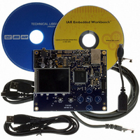
Evaluation Board, Software and Documentation
Processor To Be Evaluated
AT32UC3A0512
Processor Series
AVR
Data Bus Width
32 bit
Interface Type
USART, TWI, USB, SPI, Ethernet
Operating Supply Voltage
3.3 V
Silicon Manufacturer
Atmel
Core Architecture
AVR
Core Sub-architecture
AVR UC3
Silicon Core Number
AT32UC3A0512
Silicon Family Name
AVR
Kit Contents
Board CD Docs
Rohs Compliant
Yes
For Use With/related Products
AT32UC3A0
Lead Free Status / RoHS Status
Lead free / RoHS Compliant


Figure 26-17. Manchester Encoded Characters RF Transmission
Figure 26-18. ASK Modulator Output
32058J–AVR32–04/11
Uptstream Frequency F0
ASK Modulator
unipolar output
default polarity
NRZ stream
Manchester
Downstream
Upstream
encoded
Output
Emitter
Receiver
data
Fdown frequency Carrier
Fup frequency Carrier
Txd
1
The USART module is configured as a Manchester encoder/decoder. Looking at the down-
stream communication channel, Manchester encoded characters are serially sent to the RF
emitter. This may also include a user defined preamble and a start frame delimiter. Mostly, pre-
amble is used in the RF receiver to distinguish between a valid data from a transmitter and
signals due to noise. The Manchester stream is then modulated. See
for an example of ASK modulation scheme. When a logic one is sent to the ASK modulator, the
power amplifier, referred to as PA, is enabled and transmits an RF signal at downstream fre-
quency. When a logic zero is transmitted, the RF signal is turned off. If the FSK modulator is
activated, two different frequencies are used to transmit data. When a logic 1 is sent, the modu-
lator outputs an RF signal at frequency F0 and switches to F1 if the data sent is a 0. See
26-19 on page
From the receiver side, another carrier frequency is used. The RF receiver performs a bit check
operation examining demodulated data stream. If a valid pattern is detected, the receiver
switches to receiving mode. The demodulated stream is sent to the Manchester decoder.
Because of bit checking inside RF IC, the data transferred to the microcontroller is reduced by a
user-defined number of bits. The Manchester preamble length is to be defined in accordance
with the RF IC configuration.
318.
0
downstream transmitter
Upstream Receiver
RF filter
control
RF filter
control
Demod
VCO
VCO
ASK/FSK
LNA
Mod
PA
ASK/FSK
0
bi-dir
line
Configuration
Manchester
Manchester
decoder
encoder
Interface
Serial
Figure 26-18 on page 317
1
AT32UC3A
Receiver
USART
USART
Emitter
Figure
317
Related parts for ATEVK1105
Image
Part Number
Description
Manufacturer
Datasheet
Request
R

Part Number:
Description:
DEV KIT FOR AVR/AVR32
Manufacturer:
Atmel
Datasheet:

Part Number:
Description:
INTERVAL AND WIPE/WASH WIPER CONTROL IC WITH DELAY
Manufacturer:
ATMEL Corporation
Datasheet:
Part Number:
Description:
Low-Voltage Voice-Switched IC for Hands-Free Operation
Manufacturer:
ATMEL Corporation
Datasheet:
Part Number:
Description:
MONOLITHIC INTEGRATED FEATUREPHONE CIRCUIT
Manufacturer:
ATMEL Corporation
Datasheet:
Part Number:
Description:
AM-FM Receiver IC U4255BM-M
Manufacturer:
ATMEL Corporation
Datasheet:
Part Number:
Description:
Monolithic Integrated Feature Phone Circuit
Manufacturer:
ATMEL Corporation
Datasheet:
Part Number:
Description:
Multistandard Video-IF and Quasi Parallel Sound Processing
Manufacturer:
ATMEL Corporation
Datasheet:
Part Number:
Description:
High-performance EE PLD
Manufacturer:
ATMEL Corporation
Datasheet:
Part Number:
Description:
8-bit Flash Microcontroller
Manufacturer:
ATMEL Corporation
Datasheet:
Part Number:
Description:
2-Wire Serial EEPROM
Manufacturer:
ATMEL Corporation
Datasheet: