ATEVK1105 Atmel, ATEVK1105 Datasheet - Page 310
ATEVK1105
Manufacturer Part Number
ATEVK1105
Description
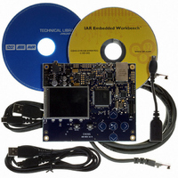
KIT EVAL FOR AT32UC3A0
Manufacturer
Atmel
Series
AVR®32r
Type
MCUr
Datasheets
1.ATAVRONE-PROBECBL.pdf
(16 pages)
2.ATEVK1104.pdf
(826 pages)
3.ATEVK1105.pdf
(28 pages)
Specifications of ATEVK1105
Contents
Evaluation Board, Software and Documentation
Processor To Be Evaluated
AT32UC3A0512
Processor Series
AVR
Data Bus Width
32 bit
Interface Type
USART, TWI, USB, SPI, Ethernet
Operating Supply Voltage
3.3 V
Silicon Manufacturer
Atmel
Core Architecture
AVR
Core Sub-architecture
AVR UC3
Silicon Core Number
AT32UC3A0512
Silicon Family Name
AVR
Kit Contents
Board CD Docs
Rohs Compliant
Yes
For Use With/related Products
AT32UC3A0
Lead Free Status / RoHS Status
Lead free / RoHS Compliant


26.7.3
26.7.3.1
Figure 26-6. Character Transmit
Figure 26-7. Transmitter Status
32058J–AVR32–04/11
Synchronous and Asynchronous Modes
Transmitter Operations
Baud Rate
TXEMPTY
Baud Rate
Example: 8-bit, Parity Enabled One Stop
US_THR
TXRDY
Clock
Write
Clock
TXD
TXD
The transmitter performs the same in both synchronous and asynchronous operating modes
(SYNC = 0 or SYNC = 1). One start bit, up to 9 data bits, one optional parity bit and up to two
stop bits are successively shifted out on the TXD pin at each falling edge of the programmed
serial clock.
The number of data bits is selected by the CHRL field and the MODE 9 bit in the Mode Register
(MR). Nine bits are selected by setting the MODE 9 bit regardless of the CHRL field. The parity
bit is set according to the PAR field in MR. The even, odd, space, marked or none parity bit can
be configured. The MSBF field in MR configures which data bit is sent first. If written at 1, the
most significant bit is sent first. At 0, the less significant bit is sent first. The number of stop bits is
selected by the NBSTOP field in MR. The 1.5 stop bit is supported in asynchronous mode only.
The characters are sent by writing in the Transmit Holding Register (THR). The transmitter
reports two status bits in the Channel Status Register (CSR): TXRDY (Transmitter Ready),
which indicates that THR is empty and TXEMPTY, which indicates that all the characters written
in THR have been processed. When the current character processing is completed, the last
character written in THR is transferred into the Shift Register of the transmitter and THR
becomes empty, thus TXRDY rises.
Both TXRDY and TXEMPTY bits are low when the transmitter is disabled. Writing a character in
THR while TXRDY is low has no effect and the written character is lost.
Start
Bit
Start
Bit
D0
D1
D0
D2
D3
D1
D4
D5
D2
D6
D7
D3
Parity
Bit
Stop
Bit
D4
Start
Bit
D0
D5
D1
D2
D6
D3
D4
D7
D5
D6
Parity
Bit
D7
Parity
Bit
Stop
Bit
Stop
Bit
AT32UC3A
310
Related parts for ATEVK1105
Image
Part Number
Description
Manufacturer
Datasheet
Request
R

Part Number:
Description:
DEV KIT FOR AVR/AVR32
Manufacturer:
Atmel
Datasheet:

Part Number:
Description:
INTERVAL AND WIPE/WASH WIPER CONTROL IC WITH DELAY
Manufacturer:
ATMEL Corporation
Datasheet:
Part Number:
Description:
Low-Voltage Voice-Switched IC for Hands-Free Operation
Manufacturer:
ATMEL Corporation
Datasheet:
Part Number:
Description:
MONOLITHIC INTEGRATED FEATUREPHONE CIRCUIT
Manufacturer:
ATMEL Corporation
Datasheet:
Part Number:
Description:
AM-FM Receiver IC U4255BM-M
Manufacturer:
ATMEL Corporation
Datasheet:
Part Number:
Description:
Monolithic Integrated Feature Phone Circuit
Manufacturer:
ATMEL Corporation
Datasheet:
Part Number:
Description:
Multistandard Video-IF and Quasi Parallel Sound Processing
Manufacturer:
ATMEL Corporation
Datasheet:
Part Number:
Description:
High-performance EE PLD
Manufacturer:
ATMEL Corporation
Datasheet:
Part Number:
Description:
8-bit Flash Microcontroller
Manufacturer:
ATMEL Corporation
Datasheet:
Part Number:
Description:
2-Wire Serial EEPROM
Manufacturer:
ATMEL Corporation
Datasheet: