ATEVK1105 Atmel, ATEVK1105 Datasheet - Page 739
ATEVK1105
Manufacturer Part Number
ATEVK1105
Description
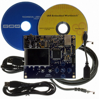
KIT EVAL FOR AT32UC3A0
Manufacturer
Atmel
Series
AVR®32r
Type
MCUr
Datasheets
1.ATAVRONE-PROBECBL.pdf
(16 pages)
2.ATEVK1104.pdf
(826 pages)
3.ATEVK1105.pdf
(28 pages)
Specifications of ATEVK1105
Contents
Evaluation Board, Software and Documentation
Processor To Be Evaluated
AT32UC3A0512
Processor Series
AVR
Data Bus Width
32 bit
Interface Type
USART, TWI, USB, SPI, Ethernet
Operating Supply Voltage
3.3 V
Silicon Manufacturer
Atmel
Core Architecture
AVR
Core Sub-architecture
AVR UC3
Silicon Core Number
AT32UC3A0512
Silicon Family Name
AVR
Kit Contents
Board CD Docs
Rohs Compliant
Yes
For Use With/related Products
AT32UC3A0
Lead Free Status / RoHS Status
Lead free / RoHS Compliant


35.4.3.2
35.4.3.3
35.4.3.4
35.4.3.5
35.4.3.6
32058J–AVR32–04/11
Program Trace
Data Trace
Ownership Trace
Watchpoint messages
Event In and Event Out pins
The trace features can be configured to be very selective, to reduce the bandwidth on the AUX
port. In case the transmit queue overflows, error messages are produced to indicate loss of
data. The transmit queue module can optionally be configured to halt the CPU when an overflow
occurs, to prevent the loss of messages, at the expense of longer run-time for the program.
Program trace allows the debugger to continuously monitor the program execution in the CPU.
Program trace messages are generated for every branch in the program, and contains com-
pressed information, which allows the debugger to correlate the message with the source code
to identify the branch instruction and target address.
Data trace outputs a message every time a specific location is read or written. The message
contains information about the type (read/write) and size of the access, as well as the address
and data of the accessed location. The AT32UC3A contains two data trace channels, each of
which are controlled by a pair of OCD registers which determine the range of addresses (or sin-
gle address) which should produce data trace messages.
Program and data trace operate on virtual addresses. In cases where an operating system runs
several processes in overlapping virtual memory segments, the Ownership Trace feature can be
used to identify the process switch. When the O/S activates a process, it will write the process ID
number to an OCD register, which produces an Ownership Trace Message, allowing the debug-
ger to switch context for the subsequent program and data trace messages. As the use of this
feature depends on the software running on the CPU, it can also be used to extract other types
of information from the system.
The breakpoint modules normally used to generate program and data breakpoints can also be
used to generate Watchpoint messages, allowing a debugger to monitor program and data
events without halting the CPU. Watchpoints can be enabled independently of breakpoints, so a
breakpoint module can optionally halt the CPU when the trigger condition occurs. Data trace
modules can also be configured to produce watchpoint messages instead of regular data trace
messages.
The AUX port also contains an Event In pin (EVTI_N) and an Event Out pin (EVTO_N). EVTI_N
can be used to trigger a breakpoint when an external event occurs. It can also be used to trigger
specific program and data trace synchronization messages, allowing an external event to be
correlated to the program flow.
When the CPU enters debug mode, a Debug Status message is transmitted on the trace port.
All trace messages can be timestamped when they are received by the debug tool. However,
due to the latency of the transmit queue buffering, the timestamp will not be 100% accurate. To
improve this, EVTO_N can toggle every time a message is inserted into the transmit queue,
allowing trace messages to be timestamped precisely. EVTO_N can also toggle when a break-
point module triggers, or when the CPU enters debug mode, for any reason. This can be used to
measure precisely when the respective internal event occurs.
AT32UC3A
739
Related parts for ATEVK1105
Image
Part Number
Description
Manufacturer
Datasheet
Request
R

Part Number:
Description:
DEV KIT FOR AVR/AVR32
Manufacturer:
Atmel
Datasheet:

Part Number:
Description:
INTERVAL AND WIPE/WASH WIPER CONTROL IC WITH DELAY
Manufacturer:
ATMEL Corporation
Datasheet:
Part Number:
Description:
Low-Voltage Voice-Switched IC for Hands-Free Operation
Manufacturer:
ATMEL Corporation
Datasheet:
Part Number:
Description:
MONOLITHIC INTEGRATED FEATUREPHONE CIRCUIT
Manufacturer:
ATMEL Corporation
Datasheet:
Part Number:
Description:
AM-FM Receiver IC U4255BM-M
Manufacturer:
ATMEL Corporation
Datasheet:
Part Number:
Description:
Monolithic Integrated Feature Phone Circuit
Manufacturer:
ATMEL Corporation
Datasheet:
Part Number:
Description:
Multistandard Video-IF and Quasi Parallel Sound Processing
Manufacturer:
ATMEL Corporation
Datasheet:
Part Number:
Description:
High-performance EE PLD
Manufacturer:
ATMEL Corporation
Datasheet:
Part Number:
Description:
8-bit Flash Microcontroller
Manufacturer:
ATMEL Corporation
Datasheet:
Part Number:
Description:
2-Wire Serial EEPROM
Manufacturer:
ATMEL Corporation
Datasheet: