MPC8349E-MITXE Freescale Semiconductor, MPC8349E-MITXE Datasheet - Page 30
MPC8349E-MITXE
Manufacturer Part Number
MPC8349E-MITXE
Description
BOARD REFERENCE FOR MPC8349
Manufacturer
Freescale Semiconductor
Series
PowerQUICC II™ PROr
Type
MPUr
Specifications of MPC8349E-MITXE
Contents
Module and Misc Hardware
Processor To Be Evaluated
MPC8349E
Interface Type
Ethernet, USB
Silicon Manufacturer
Freescale
Core Architecture
Power Architecture
Core Sub-architecture
PowerQUICC
Silicon Core Number
MPC83xx
Silicon Family Name
PowerQUICC II PRO
Rohs Compliant
Yes
For Use With/related Products
MPC8349E
Lead Free Status / RoHS Status
Lead free / RoHS Compliant
Other names
MPC8349E-MITXE


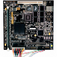
MPC8349E-mITXE Board
1.6
This section describes the operational mode and configuration options of the MPC8349-mITXE board.
1.6.1
Two banks of Flash memory can be swapped for booting the system, so each bank has its own system boot
image.
30
D3, D4, D5, D6 Hard disk activities LED. Hard disk activities indicators for HD0, HD1, HD2, and HD3, respectively.
Reference
D1/D2
D7/D8
J13
J14
J17
J19
J20
J21
J22
S3
S4
S5
D9
J7
Table 15
MPC8349E-mITXE Board Configuration
Flash Memory
RS-232 #2 select header. Selects RS-232 #2 on P16 to be connected to either CPU UART2 (Install jumpers
1–3, 2–4 as default) or MCU SCI (Install jumpers 3–5, 4–6). Alternatively, CPU UART2 can be connected to
the MCU SCI instead (Install jumpers 5–7, 6–8).
MCU POR switch header. Alternate external, chassis-mounted Reset push button for MCU firmware control.
This switch works in parallel to push button S4 on the PCB.
CPU power control jumper. Selects ATX power supply on/off to be controlled by push button S5 (jumper 2–3
as default) or MCU firmware (jumper 1–2).
MCU battery backup enable. Install jumper 1-2 to power MCU in battery standby mode. This is required if the
MCU is programmed to function as a real time clock. Do not install jumper (default) if the MCU is not
programmed to be in STOP mode while being battery powered.
CPU Power-on reset source jumper. CPU Power-On Reset can be controlled by a hardware MAX811 reset
chip (jumper 2–3 as default) or by MCU firmware (jumper 1–2).
RS-232 #2 driver power source jumpers. Selects power supply for the RS 232 #2 port on P16. Install Jumper
2–3 (default) if RS-232C #2 is used for CPU UART2 (as selected by J7). Install Jumper 1–2 if RS-232 #2 is
used for MCU communication and is powered even when CPU is shutdown (Standby mode).
Real time clock selector. CPU real time clock interrupt request can be selected from DS1339 real time clock,
[ jumper 2–3], MCU [jumper 1–2], or not selected. Default is not selected.
Reset configuration word source selection jumpers
System reset button. Resets the MPC8349E-mITXE board.
MCU reset button. Provides soft power-up and power-down of the board. The OEM can customize the
functionality in the MC9S08QG8 microcontroller firmware.
Power-on push button. Powers up the MPC8349E-mITXE board.
SW0 and SW1. Controlled by the I2C expander connected to the MPC8349E
USB port power indicator LED. Lights when power is enabled on USB port 1–4 (D7) and port 5 (D8).
3.3 V Active. On means 3.3 V power is good.
shows the jumper setting to select the Flash bank for booting the system.
Table 14. Lists of Connectors, Jumpers, Switches, and LEDs (continued)
MPC8349E-mITXE Reference Design Platform User’s Guide, Rev. 2
Preliminary—Subject to Change Without Notice
Switches
Jumpers
LEDs
Description
Freescale Semiconductor
Related parts for MPC8349E-MITXE
Image
Part Number
Description
Manufacturer
Datasheet
Request
R

Part Number:
Description:
KIT REFERENCE PLATFORM MPC8349E
Manufacturer:
Freescale Semiconductor
Datasheet:
Part Number:
Description:
KIT MODULAR DEV SYSTEM MPC8349E
Manufacturer:
Freescale Semiconductor
Datasheet:

Part Number:
Description:
MCU, MPU & DSP Development Tools PROCESSR BD MPC8349E
Manufacturer:
Freescale Semiconductor
Part Number:
Description:
MCU, MPU & DSP Development Tools KIT FOR MPC8349E BDS
Manufacturer:
Freescale Semiconductor

Part Number:
Description:
Manufacturer:
Freescale Semiconductor, Inc
Datasheet:
Part Number:
Description:
Manufacturer:
Freescale Semiconductor, Inc
Datasheet:
Part Number:
Description:
Manufacturer:
Freescale Semiconductor, Inc
Datasheet:
Part Number:
Description:
Manufacturer:
Freescale Semiconductor, Inc
Datasheet:
Part Number:
Description:
Manufacturer:
Freescale Semiconductor, Inc
Datasheet:
Part Number:
Description:
Manufacturer:
Freescale Semiconductor, Inc
Datasheet:
Part Number:
Description:
Manufacturer:
Freescale Semiconductor, Inc
Datasheet:
Part Number:
Description:
Manufacturer:
Freescale Semiconductor, Inc
Datasheet:
Part Number:
Description:
Manufacturer:
Freescale Semiconductor, Inc
Datasheet:
Part Number:
Description:
Manufacturer:
Freescale Semiconductor, Inc
Datasheet:
Part Number:
Description:
Manufacturer:
Freescale Semiconductor, Inc
Datasheet: