EVAL-AD7490CB Analog Devices Inc, EVAL-AD7490CB Datasheet - Page 21
EVAL-AD7490CB
Manufacturer Part Number
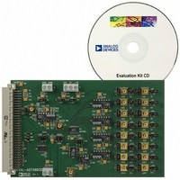
EVAL-AD7490CB
Description
BOARD EVAL FOR AD7490
Manufacturer
Analog Devices Inc
Datasheet
1.AD7490BRUZ.pdf
(28 pages)
Specifications of EVAL-AD7490CB
Number Of Adc's
1
Number Of Bits
12
Sampling Rate (per Second)
1M
Data Interface
Serial
Inputs Per Adc
16 Single Ended
Input Range
0 ~ 5 V
Power (typ) @ Conditions
12.5mW @ 1MSPS, 5 V
Voltage Supply Source
Single
Operating Temperature
-40°C ~ 85°C
Utilized Ic / Part
AD7490
Lead Free Status / RoHS Status
Contains lead / RoHS non-compliant


Powering Up the AD7490
When supplies are first applied to the AD7490, the ADC may
power up in any of the operating modes of the part. To ensure
that the part is placed into the required operating mode, the
user should perform a dummy cycle operation, as outlined in
Figure 26.
The three dummy conversion operations outlined in Figure 26
must be performed to place the part into either of the auto modes.
The first two conversions of this dummy cycle operation are
performed with the DIN line tied high, and for the third conver-
sion of the dummy cycle operation, the user should write the
desired control register configuration to the AD7490 to place
the part into the required auto mode. On the third CS rising
edge after the supplies are applied, the control register contains
the correct information and valid data results from the next
conversion.
DOUT
SCLK
DIN
CS
KEEP DIN LINE TIED HIGH FOR FIRST TWO DUMM Y CONVERSIONS
1
DUMMY CONVERSION
INVALID DATA
12
Figure 26. Placing into the Required Operating Mode After Supplies Are Applied
16
1
Rev. C | Page 21 of 28
DUMMY CONVERSION
INVALID DATA
Therefore, to ensure the part is placed into the correct operating
mode when supplies are first applied to the AD7490, the user
must first issue two serial write operations with the DIN line
tied high. On the third conversion cycle, the user can then write
to the control register to place the part into any of the operating
modes. The user should not write to the Shadow register until
the fourth conversion cycle after the supplies are applied to
the ADC to guarantee that the control register contains the
correct data.
If the user wishes to place the part into either normal mode or
full shutdown mode, the second dummy cycle with DIN tied
high can be omitted from the three dummy conversion
operation outlined in Figure 26.
12
16
1
CONTROL REGISTER IS LOADED ON THE
FIRST 12 CLOCK EDGES
DATA IN TO CONTROL
INVALID DATA
NEXT CONVERSION USER CAN
WRITE TO SHADOW REGISTER
CORRECT VALUE IN CONTROL
REGISTER VALID DATA FROM
IN NEXT CONVERSION
12
16
AD7490
Related parts for EVAL-AD7490CB
Image
Part Number
Description
Manufacturer
Datasheet
Request
R

Part Number:
Description:
ENERCHIP CC EVAL KIT
Manufacturer:
Cymbet Corporation
Datasheet:

Part Number:
Description:
BOARD EVAL FOR AD976
Manufacturer:
Analog Devices Inc
Datasheet:

Part Number:
Description:
BOARD EVAL FOR ADXL345
Manufacturer:
Analog Devices Inc
Datasheet:

Part Number:
Description:
ENERCHIP CC SEH EVAL KIT
Manufacturer:
Cymbet Corporation
Datasheet:

Part Number:
Description:
ENERCHIP EP ENERGY HARVEST EVAL
Manufacturer:
Cymbet Corporation
Datasheet:

Part Number:
Description:
EVAL BOARD FOR TW6864-LB2-GR
Manufacturer:
Intersil
Datasheet:
Part Number:
Description:
EVAL BOARD FOR TW8816-LB3-GR
Manufacturer:
Intersil
Datasheet:
Part Number:
Description:
EVAL BOARD FOR TW8817-TA3-GRS
Manufacturer:
Intersil
Datasheet:

Part Number:
Description:
EVALUATION MODULE FOR ADUM4160
Manufacturer:
Analog Devices Inc
Datasheet:

Part Number:
Description:
BOARD EVALUATION ADCMP581BCP
Manufacturer:
Analog Devices Inc
Datasheet:
Part Number:
Description:
BOARD EVALUATION ADM1041
Manufacturer:
Analog Devices Inc
Datasheet:

Part Number:
Description:
EVAL BOARD FOR STM32F107VCT
Manufacturer:
STMicroelectronics
Datasheet:
Part Number:
Description:
BOARD EVAL FOR AD1954
Manufacturer:
Analog Devices Inc
Datasheet:
Part Number:
Description:
BOARD EVAL FOR AD1955
Manufacturer:
Analog Devices Inc
Datasheet:

Part Number:
Description:
BOARD EVAL FOR AD7655
Manufacturer:
Analog Devices Inc
Datasheet: