G2R-1-SND-DC12(S) Omron, G2R-1-SND-DC12(S) Datasheet - Page 10
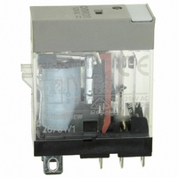
G2R-1-SND-DC12(S)
Manufacturer Part Number
G2R-1-SND-DC12(S)
Description
RELAY SPDT 12VDC PLUG-IN W/LED
Manufacturer
Omron
Series
G2RSr
Datasheets
1.G2R-1A-E-DC12.pdf
(30 pages)
2.G2R-1A-E-DC12.pdf
(14 pages)
3.G2R-1-S_DC12S.pdf
(12 pages)
Specifications of G2R-1-SND-DC12(S)
Relay Type
General Purpose
Contact Form
SPDT (1 Form C)
Contact Rating (current)
10A
Switching Voltage
440VAC, 125VDC - Max
Coil Type
Standard
Coil Current
43.2mA
Coil Voltage
12VDC
Turn On Voltage (max)
8.4 VDC
Turn Off Voltage (min)
1.8 VDC
Mounting Type
Socket
Termination Style
Quick Connect - .187" (4.7mm)
Circuit
SPDT (1 Form C)
Contact Rating @ Voltage
10A @ 250VAC
Control On Voltage (max)
8.4 VDC
Control Off Voltage (min)
1.8 VDC
Coil Voltage Vdc Nom
12V
Contact Current Max
10A
Contact Voltage Ac Nom
250V
Contact Voltage Dc Nom
30V
Coil Resistance
278ohm
Contact Configuration
SPDT
Lead Free Status / RoHS Status
Lead free / RoHS Compliant
Other names
G2R-1-SNDDC12(S)
G2R-1-SNDDC12(S)
G2R1SNDDC12S
Z2952
G2R-1-SNDDC12(S)
G2R1SNDDC12S
Z2952
Available stocks
Company
Part Number
Manufacturer
Quantity
Price
Company:

Part Number:
G2R-1-SND-DC12(S)
Manufacturer:
Omron Electronics Inc-IA Div
Quantity:
135


Precautions
■ Basic Information
Before actually committing any component to a mass-production sit-
uation, OMRON strongly recommends situational testing, in as close
to actual production situations as possible. One reason is to confirm
that the product will still perform as expected after surviving the many
handling and mounting processes that are involved in mass produc-
tion. Also, even though OMRON relays are individually tested a num-
ber of times, and each meets strict requirements, a certain testing
tolerance is permissible. When a high-precision product uses many
components, each depends upon the rated performance thresholds
of the other components. Thus, the overall performance tolerance
may accumulate into undesirable levels. To avoid problems, always
conduct tests under the actual application conditions.
General
To maintain the initial characteristics of a relay, exercise care that it is
not dropped or mishandled. For the same reason, do not remove the
case of the relay; otherwise, the characteristics may degrade. Avoid
using the relay in an atmosphere containing chemicals such as sulfu-
ric acid (SO
not continuously apply a voltage higher than the rated maximum volt-
age to the relay. Never try to operate the relay at a voltage and a cur-
rent other than those rated.
If the relay is intended for DC operation, the coil may have a polarity.
Pay particular attention to this polarity. Connect the power source to
the coil in the correct direction. Do not use the relay at temperatures
higher than that specified in the catalog or data sheet.
The storage for the relay should be in room temperature and humid-
ity.
Coil
AC-switching Relays
Generally, the coil temperature of the AC-switching relay rises higher
than that of the DC-switching relay. This is because of resistance
losses in the shading coil, eddy current losses in the magnetic circuit,
and hysteresis losses. Moreover, a phenomenon known as “chatter”
may take place when the AC-switching relay operates on a voltage
lower than that rated. For example, chatter may occur if the relay’s
supply voltage drops. This often happens when a motor (which is to
be controlled by the relay) is activated. This results in damage to the
relay contacts by burning, contact weld, or disconnection of the self-
holding circuit. Therefore, countermeasures must be taken to prevent
fluctuation in the supply voltage.
One other point that requires attention is the “inrush current.” When
the relay operates, and the armature of the relay is released from the
magnet, the impedance drops. As a result, a current much higher
than that rated flows through the coil. This current is known as the
inrush current. (When the armature is attracted to the magnet, how-
ever, the impedance rises, decreasing the inrush current to the rated
level.) Adequate consideration must be given to the inrush current,
along with the power consumption, especially when connecting sev-
eral relays in parallel.
DC-switching Relays
This type of relay is often used as a so-called “marginal” relay that
turns ON or OFF when the voltage or current reaches a critical value,
as a substitute for a meter. However, if the relay is used in this way,
its control output may fail to satisfy the ratings because the current
applied to the coil gradually increases or decreases, slowing down
the speed at which the contacts move. The coil resistance of the DC-
switching relay changes by about 0.4% per degree C change in the
ambient temperature. It also changes when the relay generates heat.
This means that the pickup and dropout voltages may increase as
the temperature rises.
Coil Operating Voltage Source
If the supply voltage fluctuates, the relay will malfunction regardless
of whether the fluctuation lasts for a long time or only for a moment.
10
2
), hydrogen sulfide (H
Electromechanical Relays
2
S), or other corrosive gases. Do
Technical Information
For example, assume that a large-capacity solenoid, relay, motor, or
heater is connected to the same power source as the relay, or that
many relays are used at the same time. If the capacity of the power
source is insufficient to operate these devices at the same time, the
relay may not operate, because the supply voltage has dropped.
Conversely, if a high voltage is applied to the relay (even after taking
voltage drop into account), chances are that the full voltage will be
applied to the relay. As a consequence, the relay’s coil will generate
heat. Therefore, be sure 1) to use a power source with sufficient
capacity and 2) that the supply voltage to the relay is within the rated
must operate voltage range of the relay.
Lower Limit Pickup Voltage
When a relay is used at high temperatures, or when the relay coil is
continuously energized, the coil temperature rises and coil resistance
increases. Consequently, the pickup voltage increases. This increase
in the pickup voltage requires attention when determining the lower-
limit pickup value of the pickup voltage. An example and outline for
determining this lower-limit pickup voltage is given below for refer-
ence when designing a power source appropriate for the relay.
Assuming a coil temperature rise of 10°C, the coil resistance will
increase about 4%. The pickup voltage increases as follows:
Rated values of Model G5LE are taken from catalog or data sheet.
Rated voltage: 12 VDC
Coil resistance: 360Ω
Pickup voltage: 75% max. of rated voltage at 23°C coil temperature
The rated current that flows through this relay can be obtained by
dividing the rated voltage by the coil resistance. Hence,
12 VDC ÷ 360Ω = 33.3 mA
However, the relay operates at 75% maximum of this rated current, i.e.,
25mA (= 33 mA x 0.75). Assuming that the coil temperature rises by
10°C, the coil resistance increases 4% to 374Ω (= 360Ω x 1.04). The
voltage that must be applied to the relay to flow an operating current of
25 mA through the relay under this condition is 25 mA x 374Ω = 9.35 V.
The minimum must operate voltage can be determined by this expression.
E
where,
E (V): Rated coil voltage
Epv (%): Must operate voltage
Ta: Coil temperature for determining Epv (20°C, unless otherwise
specified)
T (°C): Ambient operating temperature
ET (V): Minimum must operate voltage
Note: In the above expression, T is taken to be the result of energiza-
T
> E x
tion of the coil, when the coil temperature is the same as the
ambient temperature.
Epv
-------------------- -
100
+
Coil Temperature vs.
Must Operate/release Voltage
5
x (
----------------------------
234.5
Coil voltage: 24 VDC
N = 10 (mean value)
T Ta
Ambient temperature (°C)
–
+
Ta
+ 1) [V]
Must operate voltage
Must release voltage
Related parts for G2R-1-SND-DC12(S)
Image
Part Number
Description
Manufacturer
Datasheet
Request
R

Part Number:
Description:
RELAY POWER SPDT 10A 24VDC QCMNT
Manufacturer:
Omron
Datasheet:
Part Number:
Description:
RELAY SPDT 6VDC PLUG-IN W/LED
Manufacturer:
Omron
Datasheet:
Part Number:
Description:
GP Relay
Manufacturer:
Omron
Datasheet:
Part Number:
Description:
RELAY PWR SPDT 10A 12VDC QC MNT
Manufacturer:
Omron
Datasheet:
Part Number:
Description:
RELAY PWR SPDT 10A 24VDC QC MNT
Manufacturer:
Omron
Datasheet:

Part Number:
Description:
POWER RELAY, SPDT, 24VDC, 10A, PLUG IN
Manufacturer:
Omron
Datasheet:

Part Number:
Description:
POWER RELAY, SPDT, 24VDC, 10A, PLUG IN
Manufacturer:
Omron
Datasheet:
Part Number:
Description:
RELAY, SPCO, 10A, 12VDC
Manufacturer:
Omron
Datasheet:

Part Number:
Description:
POWER RELAY, SPDT, 6VDC, 10A, PLUG IN
Manufacturer:
Omron
Datasheet:

Part Number:
Description:
RELAY; E-MECH; POWER; DPDT; CUR-RTG 5A; CTRL-V 24DC; VOL-RTG 250/30AC/DC; SOCKET MNT
Manufacturer:
Omron Automation
Datasheet:

Part Number:
Description:
RELAY GP SPDT 240VAC PLUG-IN
Manufacturer:
Omron
Datasheet:

Part Number:
Description:
Relay
Manufacturer:
Omron
Datasheet: