G2R-1-SND-DC12(S) Omron, G2R-1-SND-DC12(S) Datasheet - Page 8
G2R-1-SND-DC12(S)
Manufacturer Part Number
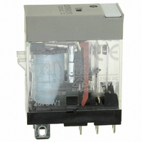
G2R-1-SND-DC12(S)
Description
RELAY SPDT 12VDC PLUG-IN W/LED
Manufacturer
Omron
Series
G2RSr
Datasheets
1.G2R-1A-E-DC12.pdf
(30 pages)
2.G2R-1A-E-DC12.pdf
(14 pages)
3.G2R-1-S_DC12S.pdf
(12 pages)
Specifications of G2R-1-SND-DC12(S)
Relay Type
General Purpose
Contact Form
SPDT (1 Form C)
Contact Rating (current)
10A
Switching Voltage
440VAC, 125VDC - Max
Coil Type
Standard
Coil Current
43.2mA
Coil Voltage
12VDC
Turn On Voltage (max)
8.4 VDC
Turn Off Voltage (min)
1.8 VDC
Mounting Type
Socket
Termination Style
Quick Connect - .187" (4.7mm)
Circuit
SPDT (1 Form C)
Contact Rating @ Voltage
10A @ 250VAC
Control On Voltage (max)
8.4 VDC
Control Off Voltage (min)
1.8 VDC
Coil Voltage Vdc Nom
12V
Contact Current Max
10A
Contact Voltage Ac Nom
250V
Contact Voltage Dc Nom
30V
Coil Resistance
278ohm
Contact Configuration
SPDT
Lead Free Status / RoHS Status
Lead free / RoHS Compliant
Other names
G2R-1-SNDDC12(S)
G2R-1-SNDDC12(S)
G2R1SNDDC12S
Z2952
G2R-1-SNDDC12(S)
G2R1SNDDC12S
Z2952
Available stocks
Company
Part Number
Manufacturer
Quantity
Price
Company:

Part Number:
G2R-1-SND-DC12(S)
Manufacturer:
Omron Electronics Inc-IA Div
Quantity:
135


■ Terms Related to Electrical
Dielectric Strength
The critical value which a dielectric can withstand without rupturing
when a high-tension voltage is applied for 1 minute between the fol-
lowing points:
• Between coil and contact
• Between contacts of different poles
• Between contacts of same poles
• Between set coil and reset coil
• Between current-carrying metal parts and ground terminal
Note that normally a leakage current of 3 mA is detected; however, a
leakage current of 1 mA to 10 mA may be detected on occasion.
Electrical Service Life
The life of a relay when it is switched at the rated operating frequency
with the rated load applied to its contacts. Also known as Electrical
Endurance.
High-frequency Isolation (Applicable to
High-frequency Relay only)
The degree of isolation of a high-frequency signal, which is equiva-
lent to the insulation resistance of ordinary relays.
The following characteristics are measured with contacts unrelated
to the measurement terminated at 50Ω, when a signal is applied from
input terminal 11 to output terminal 8 or from input terminal 11 to out-
put terminal 14 of the sample.
• Isolation characteristics
• Insertion loss characteristics
• Return loss
The following conversion formula converts from return loss to VSWR.
High-frequency Switching Power
(Applicable to High-frequency Relays
Only)
The power of a high-frequency signal that can be switched.
8
Characteristics
OUT
Electromechanical Relays
HP8505A
network
analyzer
G5Y-154P
IN
HP8502A
transmission test set
VSWR =
where,
x = return loss
OUT
HP8501A
storage
normalizer
1 + 10
1 − 10
50-Ω termination
resistances
−
−
20
20
x
x
Technical Information
High-frequency Transmitted Power
(Applicable to High-frequency Relays
Only)
The transmission capacity of a high-frequency signal.
Impulse Withstand Voltage
The critical value which the relay can withstand when the voltage
surges momentarily due to lightning, switching an inductive load, etc.
The surge waveform which has a pulse width of ±1.2 x 50 μs is
shown below:
Insertion Loss (Applicable to High-
frequency Relays Only)
The attenuation of a high-frequency signal in a transmission line and
is equivalent to the contact resistance of ordinary relays.
Insulation Resistance
The resistance between an electric circuit such as the contacts and
coil, and grounded, non-conductive metal parts such as the core, or
the resistance between the contacts. The measured values are as
follows:
Maximum Operating Frequency
The frequency or intervals at which the relay continuously operates
and releases, satisfying the rated mechanical and electrical service
life.
Mechanical Service Life
The life of a relay when it is switched at the rated operating frequency
without the rated load. Also known as Mechanical Endurance.
Operate Bounce Time
The bounce time of the normally open (NO) contact of a relay when
the rated coil voltage is applied to the relay coil at an ambient tem-
perature of 23°C.
Operate Time
The time that elapses after power is applied to a relay coil until the
NO contacts have closed, at an ambient temperature of 23°C.
Bounce time is not included. For the relays having an operate time of
less than 10 ms, the mean (reference) value of its operate time is
specified as follows:
60 V max.
61 V min.
Operate time
Rated insulation voltage
5 ms max. (mean value: approx. 2.3 ms)
250 V
500 V
Peak value
Time (ms)
Measured value
Related parts for G2R-1-SND-DC12(S)
Image
Part Number
Description
Manufacturer
Datasheet
Request
R

Part Number:
Description:
RELAY POWER SPDT 10A 24VDC QCMNT
Manufacturer:
Omron
Datasheet:
Part Number:
Description:
RELAY SPDT 6VDC PLUG-IN W/LED
Manufacturer:
Omron
Datasheet:
Part Number:
Description:
GP Relay
Manufacturer:
Omron
Datasheet:
Part Number:
Description:
RELAY PWR SPDT 10A 12VDC QC MNT
Manufacturer:
Omron
Datasheet:
Part Number:
Description:
RELAY PWR SPDT 10A 24VDC QC MNT
Manufacturer:
Omron
Datasheet:

Part Number:
Description:
POWER RELAY, SPDT, 24VDC, 10A, PLUG IN
Manufacturer:
Omron
Datasheet:

Part Number:
Description:
POWER RELAY, SPDT, 24VDC, 10A, PLUG IN
Manufacturer:
Omron
Datasheet:
Part Number:
Description:
RELAY, SPCO, 10A, 12VDC
Manufacturer:
Omron
Datasheet:

Part Number:
Description:
POWER RELAY, SPDT, 6VDC, 10A, PLUG IN
Manufacturer:
Omron
Datasheet:

Part Number:
Description:
RELAY; E-MECH; POWER; DPDT; CUR-RTG 5A; CTRL-V 24DC; VOL-RTG 250/30AC/DC; SOCKET MNT
Manufacturer:
Omron Automation
Datasheet:

Part Number:
Description:
RELAY GP SPDT 240VAC PLUG-IN
Manufacturer:
Omron
Datasheet:

Part Number:
Description:
Relay
Manufacturer:
Omron
Datasheet: