G2R-1-SND-DC12(S) Omron, G2R-1-SND-DC12(S) Datasheet - Page 27
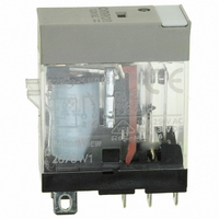
G2R-1-SND-DC12(S)
Manufacturer Part Number
G2R-1-SND-DC12(S)
Description
RELAY SPDT 12VDC PLUG-IN W/LED
Manufacturer
Omron
Series
G2RSr
Datasheets
1.G2R-1A-E-DC12.pdf
(30 pages)
2.G2R-1A-E-DC12.pdf
(14 pages)
3.G2R-1-S_DC12S.pdf
(12 pages)
Specifications of G2R-1-SND-DC12(S)
Relay Type
General Purpose
Contact Form
SPDT (1 Form C)
Contact Rating (current)
10A
Switching Voltage
440VAC, 125VDC - Max
Coil Type
Standard
Coil Current
43.2mA
Coil Voltage
12VDC
Turn On Voltage (max)
8.4 VDC
Turn Off Voltage (min)
1.8 VDC
Mounting Type
Socket
Termination Style
Quick Connect - .187" (4.7mm)
Circuit
SPDT (1 Form C)
Contact Rating @ Voltage
10A @ 250VAC
Control On Voltage (max)
8.4 VDC
Control Off Voltage (min)
1.8 VDC
Coil Voltage Vdc Nom
12V
Contact Current Max
10A
Contact Voltage Ac Nom
250V
Contact Voltage Dc Nom
30V
Coil Resistance
278ohm
Contact Configuration
SPDT
Lead Free Status / RoHS Status
Lead free / RoHS Compliant
Other names
G2R-1-SNDDC12(S)
G2R-1-SNDDC12(S)
G2R1SNDDC12S
Z2952
G2R-1-SNDDC12(S)
G2R1SNDDC12S
Z2952
Available stocks
Company
Part Number
Manufacturer
Quantity
Price
Company:

Part Number:
G2R-1-SND-DC12(S)
Manufacturer:
Omron Electronics Inc-IA Div
Quantity:
135


If applied voltage E and the rated coil voltage of the relay are the
same, the current to the relay falls short by the quantity indicated by
the shaded portion in the following figure.
Therefore, the current must be applied to the relay as follows when
designing this driver circuit.
Time constant
When the rated voltage is applied to the relay, time A in the timing
chart below is required to turn ON the contacts. After this time has
elapsed, time B is required until the armature attraction to the mag-
net is complete.
Therefore, it is apparent that time constant T obtained as the product
of C and R must be equal to or longer than the sum of A and B. Actu-
ally, however, T should not be equal to the sum of A and B but must
be longer than that to ensure the stable operation of the circuit. Thus,
T = A + B + X
where X is the time margin.
The set time A of OMRON’s moving-loop relays (with a pickup power
of 200 mW) is rated at about 3 milliseconds. Time constant T for
them should be about three times that of A. The following graph illus-
trates this. This graph indicates that, if C is completely charged
(I
broken down into three segments. The first 1/3T equals A, the sec-
ond 1/3T, B. The remaining 1/3T is the time margin expressed as X in
the above equation. T is three times A.
Voltage drop E1 across the total resistance of the capacitance C’s
resistance and relay coil’s internal resistance is the difference
between the supply voltage E and voltage drops across two
diodes: Di1 and Di2. Hence,
E1 = E – 2VF
Assuming the supply voltage to be 5 V and VF to be 0.6 V,
E1 = 5 – 2 x 0.6 = 3.8 V
From E1 and the above graph, the required coil voltage of a relay can
be obtained. Again assuming the E, i.e., the supply voltage of a sin-
gle-winding latching relay is 5 V, the coil voltage is:
3.8 x 0.72 = 2.7 V
At this time, the capacitance of C is 246.9 μF, according to the equa-
tion shown in the above graph.
PEAK
), it takes 4.6T to discharge I to 1%. Note that time constant T is
E
Applied voltage
Contact ON
Attraction of
armature
E
Coil voltage
2VF
2VF
Pulse width and current
necessary for setting relay
A
B
Set time
Time required to set
relay completely
4.5T
Electromechanical Relays
Coil ratings and capacitance of C
In the example, the coil voltage obtained by calculation is 2.7 V,
which is 0.3 V less than the value at which the coil voltage of com-
mercially available standard latching relay is rated. The standard coil
voltages of relays at a supply voltage of 6, 9, 12, and 24 V can be
respectively calculated in the same way. Table 1 compares the
results of the calculation and the coil voltages of standard relays.
The calculated coil voltages significantly deviates from the standard
values. It is therefore necessary to determine the time constant of the
relay by adjusting the capacitance of C when the relay coil is to oper-
ate on the standard voltage.
As an example, calculate the capacitance of C and time constant T of
a relay with a rated supply voltage of 5 V. The coil voltage E
been calculated above (3.8 V). To determine how much current I
flows through the coil at 3.8 V, from Table 1, note that the coil resis-
tance is 45Ω. So,
I = 3.8/45 = 84.4 mA
Therefore, the peak current of capacitor C to be used must be
84.4 mA.
Remember, that time A of an OMRON relay is 3 ms. Capacitance C
must be a value that allows 66.6 mA to flow through 3 ms after 5 V is
applied to the relay.
Thus,
From this,
C = 280 μF
At this time, time constant T is:
280 x 10
By calculating the C of each of the relays listed in Table 1, the values
in Table 2 are obtained.
Again, these calculated capacitances deviate from the commercially
available standard capacitors. There is no problem in using standard
capacitors but, if the cost and circuit space permit, it is recommended
to use two or more capacitors so that a capacitance as close to the
calculated value as possible is obtained. At this time, pay attention to
the following points:
• Confirm that the relay operates normally even when the supply volt-
• Even if a voltage of two or three times the rated voltage is applied to
Supply voltage
Supply voltage
age is brought to 80%-120% of the rated value.
this driver circuit, the coil wire will not sever. That is why, for exam-
ple, when the driver circuit is mounted in an automobile where a
supply voltage of 12 VDC is available from the battery, it is recom-
mended to use a relay whose coil voltage is rated at 6 VDC, taking
a voltage fluctuation of 8 to 16 VDC into consideration.
12 V
24 V
12 V
24 V
5 V
6 V
9 V
5 V
6 V
9 V
–6
x 45 = 12.6 ms
Technical Information
Coil voltage
Coil voltage
(calculated)
(calculated)
16.4 V
16.4 V
2.7 V
3.5 V
5.6 V
7.8 V
2.7 V
3.5 V
5.6 V
7.8 V
Table 1
Table 2
resistance
Standard
voltage
125Ω
720Ω
405Ω
12 V
Coil
45Ω
45Ω
3 V
3 V
5 V
6 V
Capacitance
resistance
280 μF
142 μF
6.5 μF
125Ω
405Ω
720Ω
54 μF
40 μF
of C
Coil
45Ω
45Ω
27
1
has
Related parts for G2R-1-SND-DC12(S)
Image
Part Number
Description
Manufacturer
Datasheet
Request
R

Part Number:
Description:
RELAY POWER SPDT 10A 24VDC QCMNT
Manufacturer:
Omron
Datasheet:
Part Number:
Description:
RELAY SPDT 6VDC PLUG-IN W/LED
Manufacturer:
Omron
Datasheet:
Part Number:
Description:
GP Relay
Manufacturer:
Omron
Datasheet:
Part Number:
Description:
RELAY PWR SPDT 10A 12VDC QC MNT
Manufacturer:
Omron
Datasheet:
Part Number:
Description:
RELAY PWR SPDT 10A 24VDC QC MNT
Manufacturer:
Omron
Datasheet:

Part Number:
Description:
POWER RELAY, SPDT, 24VDC, 10A, PLUG IN
Manufacturer:
Omron
Datasheet:

Part Number:
Description:
POWER RELAY, SPDT, 24VDC, 10A, PLUG IN
Manufacturer:
Omron
Datasheet:
Part Number:
Description:
RELAY, SPCO, 10A, 12VDC
Manufacturer:
Omron
Datasheet:

Part Number:
Description:
POWER RELAY, SPDT, 6VDC, 10A, PLUG IN
Manufacturer:
Omron
Datasheet:

Part Number:
Description:
RELAY; E-MECH; POWER; DPDT; CUR-RTG 5A; CTRL-V 24DC; VOL-RTG 250/30AC/DC; SOCKET MNT
Manufacturer:
Omron Automation
Datasheet:

Part Number:
Description:
RELAY GP SPDT 240VAC PLUG-IN
Manufacturer:
Omron
Datasheet:

Part Number:
Description:
Relay
Manufacturer:
Omron
Datasheet: