G2R-1-SND-DC12(S) Omron, G2R-1-SND-DC12(S) Datasheet - Page 7
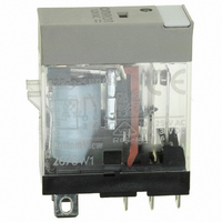
G2R-1-SND-DC12(S)
Manufacturer Part Number
G2R-1-SND-DC12(S)
Description
RELAY SPDT 12VDC PLUG-IN W/LED
Manufacturer
Omron
Series
G2RSr
Datasheets
1.G2R-1A-E-DC12.pdf
(30 pages)
2.G2R-1A-E-DC12.pdf
(14 pages)
3.G2R-1-S_DC12S.pdf
(12 pages)
Specifications of G2R-1-SND-DC12(S)
Relay Type
General Purpose
Contact Form
SPDT (1 Form C)
Contact Rating (current)
10A
Switching Voltage
440VAC, 125VDC - Max
Coil Type
Standard
Coil Current
43.2mA
Coil Voltage
12VDC
Turn On Voltage (max)
8.4 VDC
Turn Off Voltage (min)
1.8 VDC
Mounting Type
Socket
Termination Style
Quick Connect - .187" (4.7mm)
Circuit
SPDT (1 Form C)
Contact Rating @ Voltage
10A @ 250VAC
Control On Voltage (max)
8.4 VDC
Control Off Voltage (min)
1.8 VDC
Coil Voltage Vdc Nom
12V
Contact Current Max
10A
Contact Voltage Ac Nom
250V
Contact Voltage Dc Nom
30V
Coil Resistance
278ohm
Contact Configuration
SPDT
Lead Free Status / RoHS Status
Lead free / RoHS Compliant
Other names
G2R-1-SNDDC12(S)
G2R-1-SNDDC12(S)
G2R1SNDDC12S
Z2952
G2R-1-SNDDC12(S)
G2R1SNDDC12S
Z2952
Available stocks
Company
Part Number
Manufacturer
Quantity
Price
Company:

Part Number:
G2R-1-SND-DC12(S)
Manufacturer:
Omron Electronics Inc-IA Div
Quantity:
135


The life expectancy of the relay can be determined from the electrical
service life curve shown below, based on the rated switching current
(I
obtained maximum switching current of 2 A is slightly over 300,000
operations (see circled point on graph below).
However, with a DC load, it may become difficult to break the circuit
of 48 V or more due to arcing. Determine the suitability of the relay in
actual usage testing.
The correlation between the contact ratings is shown in the following
figure:
Minimum Permissible Load
The minimum permissible load indicates the lower limit of switching
capability of a relay as the reference value. Such minute load levels
are found in microelectronic circuits. This value may vary, depending
on operating frequency, operating conditions, expected reliability
level of the relay, etc. It is always recommended to double-check
relay suitability under actual load conditions.
In Omron catalogs, the minimum permissible load of each relay is
indicated as a reference value. It indicates failure level at a reliability
level of 60% (λ
presumed to occur per 10,000,000 (ten million) operations at a reli-
ability level of 60%.
Number of Poles
The number of contact circuits. See Contact Form for reference.
1
) obtained above. For instance, the electrical service life at the
60
). λ
60
=0.1x 10
Operating current (A)
Operating voltage (V)
-6
/operation means that one failure is
Switching capacity
W max.
VA max.
Electromechanical Relays
■ Terms Related to Coils
Rated Coil Voltage
A reference voltage applied to the coil when the relay is used under
normal operating conditions.
Coil Symbols
Coil Resistance (Applicable to
DC-switching Relays only)
The resistance of the coil is measured at a temperature of 23°C with
a tolerance of ±10% unless otherwise specified. (The coil resistance
of an AC-switching type relay may be given for reference when the
coil inductance is specified.)
Cold Start
The ratings set forth in the catalog or data sheet are measured at a
coil temperature of 23°C unless otherwise specified.
Maximum Voltage
The maximum value of permissible over voltage or pulsating voltage
fluctuations in the operating power supply to the relay coil.
Minimum Pulse Width
The minimum value of the pulse voltage required to set and reset a
latching relay at a temperature of 23°C.
Must Operate (Must Set) Voltage
The threshold value of a voltage at which a relay operates when the
input voltage applied to the relay coil in the reset state is increased
gradually.
Must Release (Must Reset) Voltage
The threshold value of a voltage at which a relay releases when the
rated input voltage applied to the relay coil in the operating state is
decreased gradually.
Power Consumption
The power (= rated voltage x rated current) consumed by the coil
when the rated voltage is applied to it. A frequency of 60 Hz is
assumed if the relay is intended for AC operation. The current flows
through the coil when the rated voltage is applied to the coil at a tem-
perature of 23°C. The tolerance is +15%/-20% unless otherwise
specified.
Polarized
Single-sided stable
(Non-latching)
+
−
Technical Information
polarized
Non-
terminals
S
w/4
+
−
R
Dual Coil
Latching
+
−
S
terminals
+
w/3
−
R
+
−
Single Coil
Latching
S
+
−
−
+
R
7
Related parts for G2R-1-SND-DC12(S)
Image
Part Number
Description
Manufacturer
Datasheet
Request
R

Part Number:
Description:
RELAY POWER SPDT 10A 24VDC QCMNT
Manufacturer:
Omron
Datasheet:
Part Number:
Description:
RELAY SPDT 6VDC PLUG-IN W/LED
Manufacturer:
Omron
Datasheet:
Part Number:
Description:
GP Relay
Manufacturer:
Omron
Datasheet:
Part Number:
Description:
RELAY PWR SPDT 10A 12VDC QC MNT
Manufacturer:
Omron
Datasheet:
Part Number:
Description:
RELAY PWR SPDT 10A 24VDC QC MNT
Manufacturer:
Omron
Datasheet:

Part Number:
Description:
POWER RELAY, SPDT, 24VDC, 10A, PLUG IN
Manufacturer:
Omron
Datasheet:

Part Number:
Description:
POWER RELAY, SPDT, 24VDC, 10A, PLUG IN
Manufacturer:
Omron
Datasheet:
Part Number:
Description:
RELAY, SPCO, 10A, 12VDC
Manufacturer:
Omron
Datasheet:

Part Number:
Description:
POWER RELAY, SPDT, 6VDC, 10A, PLUG IN
Manufacturer:
Omron
Datasheet:

Part Number:
Description:
RELAY; E-MECH; POWER; DPDT; CUR-RTG 5A; CTRL-V 24DC; VOL-RTG 250/30AC/DC; SOCKET MNT
Manufacturer:
Omron Automation
Datasheet:

Part Number:
Description:
RELAY GP SPDT 240VAC PLUG-IN
Manufacturer:
Omron
Datasheet:

Part Number:
Description:
Relay
Manufacturer:
Omron
Datasheet: