G2R-1-SND-DC12(S) Omron, G2R-1-SND-DC12(S) Datasheet - Page 11
G2R-1-SND-DC12(S)
Manufacturer Part Number
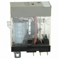
G2R-1-SND-DC12(S)
Description
RELAY SPDT 12VDC PLUG-IN W/LED
Manufacturer
Omron
Series
G2RSr
Datasheets
1.G2R-1A-E-DC12.pdf
(30 pages)
2.G2R-1A-E-DC12.pdf
(14 pages)
3.G2R-1-S_DC12S.pdf
(12 pages)
Specifications of G2R-1-SND-DC12(S)
Relay Type
General Purpose
Contact Form
SPDT (1 Form C)
Contact Rating (current)
10A
Switching Voltage
440VAC, 125VDC - Max
Coil Type
Standard
Coil Current
43.2mA
Coil Voltage
12VDC
Turn On Voltage (max)
8.4 VDC
Turn Off Voltage (min)
1.8 VDC
Mounting Type
Socket
Termination Style
Quick Connect - .187" (4.7mm)
Circuit
SPDT (1 Form C)
Contact Rating @ Voltage
10A @ 250VAC
Control On Voltage (max)
8.4 VDC
Control Off Voltage (min)
1.8 VDC
Coil Voltage Vdc Nom
12V
Contact Current Max
10A
Contact Voltage Ac Nom
250V
Contact Voltage Dc Nom
30V
Coil Resistance
278ohm
Contact Configuration
SPDT
Lead Free Status / RoHS Status
Lead free / RoHS Compliant
Other names
G2R-1-SNDDC12(S)
G2R-1-SNDDC12(S)
G2R1SNDDC12S
Z2952
G2R-1-SNDDC12(S)
G2R1SNDDC12S
Z2952
Available stocks
Company
Part Number
Manufacturer
Quantity
Price
Company:

Part Number:
G2R-1-SND-DC12(S)
Manufacturer:
Omron Electronics Inc-IA Div
Quantity:
135


■ Coil Input
To guarantee accurate and stable relay operation, the first and fore-
most condition to be satisfied is the application of the rated voltage to
the relay. Additionally, details concerning the type of the power
source, voltage fluctuation, changes in coil resistance due to temper-
ature rise and the rated voltage must also be considered. If a voltage
higher than the rated maximum voltage is applied to the coil for a
long time, layer short-circuiting and damage to the coil by burning
may take place.
Coil Temperature Rise
When a current flows through the coil, the coil’s temperature rises to
a measurable level, because of copper loss. If an alternating current
flows, the temperature rises even more, due not only to the copper
loss, but additionally to the iron loss of the magnetic materials, such
as the core. Moreover, when a current is applied to the contact, heat
is generated on the contacts, raising the coil temperature even higher
(however, with relays whose switching current is rated at 2 A or lower,
this rise is insignificant).
Temperature Rise by Pulsating Voltage
When a pulsating voltage having an ON time of less than 2 minutes
is applied to the relay, the coil temperature rise varies, and is inde-
pendent of the duration of the ON time, depending only on the ratio of
the ON time to the OFF time. The coil temperature in this case does
not rise as high as when a voltage is continuously applied to the
relay.
Changes in Must Operate Voltage by
Coil Temperature Rise (Hot Start)
The coil resistance of a DC-switching relay increases (as the coil
temperature rises) when the coil has been continuously energized,
de-energized once, and then immediately energized again. This
increase in the coil resistance raises the voltage value at which the
relay operates. Additionally, the coil resistance rises when the relay is
used at a high ambient temperature.
Maximum Must Operate Voltage
The maximum voltage applicable to a relay is determined in accor-
dance with the coil temperature rise and the coil insulation materials’
heat resistivity, electrical as well as mechanical life, general charac-
teristics, and other factors.
If a voltage exceeding the maximum voltage is applied to the relay, it
may cause the insulation materials to degrade, the coil to be burnt,
and the relay to malfunction at normal levels.
The coil temperature must not exceed the temperature that the coil
can withstand.
Continuous energization
ON:OFF = 3:1 approx.
ON:OFF = 1:1 approx.
ON:OFF = 1:3 approx.
Energization time
(V)
1:1
100%
80%
50%
35%
(t)
Release temperature rise
Electromechanical Relays
How to Calculate Coil Temperature
where,
Before using the relay confirm no problems occur.
DC Input Power Source
Pay attention to the coil polarity of the DC-switching relay. Power
sources for DC-operated relays are usually a battery or a DC power
supply, either with a maximum ripple of 5%. If power is supplied to
the relay via a rectifier, the pickup and dropout voltages vary with the
ripple percentage. Therefore, check the voltages before actually
using the relay. If the ripple component is extremely large, chatter
may occur. If this happens, it is recommended that a smoothing
capacitor be inserted as shown in the following diagram.
The use of a regulated, filtered power supply is preferred for DC
coils.
If the voltage applied to the DC-operated coil increases or decreases
slowly, each contact of a multi-pole contact relay may not operate at
the same time. It is also possible for this situation to result in the must
operate voltage varying each time the relay operates. Either way, cir-
cuit sequencing will not be correct. In critical applications, the use of
a Schmitt circuit is recommended to reshape the DC waveform to
trigger all contacts of the relay at the same time.
R1 Ω:
R2 Ω:
T1 (°C):
t (°C):
t =
R2 R1
--------------------- -
R1
–
Ripple percentage =
where,
E max.: maximum value of ripple component
E min.: minimum value of ripple component
E mean: mean value of DC component
Technical Information
(234.5+T1) + T1 [°C]
coil resistance before energization
coil resistance after energization
coil temperature (ambient) before energization
coil temperature after energization
E min.
E max. E mean
Emax. − Emin.
Smoothing capacitor
Emean
Ripple component
x 100
DC component
Relay
11
Related parts for G2R-1-SND-DC12(S)
Image
Part Number
Description
Manufacturer
Datasheet
Request
R

Part Number:
Description:
RELAY POWER SPDT 10A 24VDC QCMNT
Manufacturer:
Omron
Datasheet:
Part Number:
Description:
RELAY SPDT 6VDC PLUG-IN W/LED
Manufacturer:
Omron
Datasheet:
Part Number:
Description:
GP Relay
Manufacturer:
Omron
Datasheet:
Part Number:
Description:
RELAY PWR SPDT 10A 12VDC QC MNT
Manufacturer:
Omron
Datasheet:
Part Number:
Description:
RELAY PWR SPDT 10A 24VDC QC MNT
Manufacturer:
Omron
Datasheet:

Part Number:
Description:
POWER RELAY, SPDT, 24VDC, 10A, PLUG IN
Manufacturer:
Omron
Datasheet:

Part Number:
Description:
POWER RELAY, SPDT, 24VDC, 10A, PLUG IN
Manufacturer:
Omron
Datasheet:
Part Number:
Description:
RELAY, SPCO, 10A, 12VDC
Manufacturer:
Omron
Datasheet:

Part Number:
Description:
POWER RELAY, SPDT, 6VDC, 10A, PLUG IN
Manufacturer:
Omron
Datasheet:

Part Number:
Description:
RELAY; E-MECH; POWER; DPDT; CUR-RTG 5A; CTRL-V 24DC; VOL-RTG 250/30AC/DC; SOCKET MNT
Manufacturer:
Omron Automation
Datasheet:

Part Number:
Description:
RELAY GP SPDT 240VAC PLUG-IN
Manufacturer:
Omron
Datasheet:

Part Number:
Description:
Relay
Manufacturer:
Omron
Datasheet: