G2R-1-SND-DC12(S) Omron, G2R-1-SND-DC12(S) Datasheet - Page 22
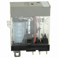
G2R-1-SND-DC12(S)
Manufacturer Part Number
G2R-1-SND-DC12(S)
Description
RELAY SPDT 12VDC PLUG-IN W/LED
Manufacturer
Omron
Series
G2RSr
Datasheets
1.G2R-1A-E-DC12.pdf
(30 pages)
2.G2R-1A-E-DC12.pdf
(14 pages)
3.G2R-1-S_DC12S.pdf
(12 pages)
Specifications of G2R-1-SND-DC12(S)
Relay Type
General Purpose
Contact Form
SPDT (1 Form C)
Contact Rating (current)
10A
Switching Voltage
440VAC, 125VDC - Max
Coil Type
Standard
Coil Current
43.2mA
Coil Voltage
12VDC
Turn On Voltage (max)
8.4 VDC
Turn Off Voltage (min)
1.8 VDC
Mounting Type
Socket
Termination Style
Quick Connect - .187" (4.7mm)
Circuit
SPDT (1 Form C)
Contact Rating @ Voltage
10A @ 250VAC
Control On Voltage (max)
8.4 VDC
Control Off Voltage (min)
1.8 VDC
Coil Voltage Vdc Nom
12V
Contact Current Max
10A
Contact Voltage Ac Nom
250V
Contact Voltage Dc Nom
30V
Coil Resistance
278ohm
Contact Configuration
SPDT
Lead Free Status / RoHS Status
Lead free / RoHS Compliant
Other names
G2R-1-SNDDC12(S)
G2R-1-SNDDC12(S)
G2R1SNDDC12S
Z2952
G2R-1-SNDDC12(S)
G2R1SNDDC12S
Z2952
Available stocks
Company
Part Number
Manufacturer
Quantity
Price
Company:

Part Number:
G2R-1-SND-DC12(S)
Manufacturer:
Omron Electronics Inc-IA Div
Quantity:
135


Notes on Correct Use
■ Driving by Transistor
When a transistor is used to drive the relay, be sure to ground the emitter of the transistor.
When the transistor is used in emitter-follower configuration (i.e., the collector is grounded), give adequate consideration to the voltage across the
collector and emitter. The required voltage must be applied to the relay.
NPN transistor
Advice on selecting a transistor for driving the relay
1. From the relay catalog or data sheet, ascertain the following coil
2. Determine the lower- and upper-limit values of the pickup voltage
3. By determining the component for suppressing surge, obtain the dielectric strength of the transistor for driving the relay.
4. Determine collector current l
5. Select the transistor that satisfies the conditions determined in
6. After selecting the transistor, observe the l
22
characteristics:
Rated voltage ________ VDC
Rated current ________ mA
Coil resistance _______ Ω
from the rated voltage.
Lower-limit pickup voltage _____V
Upper-limit pickup voltage _____V
(If surge is contained in the rated voltage, obtain the maximum
value including the surge.)
In the case of diode
(Upper-limit of pickup voltage + 0.6) x 2* ≅ V
In the case of diode and zener diode
(Upper-limit of pickup voltage + 0.6 + breakdown voltage**) x 2* ≅ V
In the case of varistor
(Upper-limit pickup voltage + varistor voltage***) x 2* ≅ V
In the case of RC
(Upper-limit pickup voltage + surge voltage****) x 2* ≅ V
l
steps 3 and 4.
of the transistor indicated in its ratings.
The characteristic curve illustrates the relation between collector
current l
From this graph, obtain collector-emitter voltage V
l
l
by the driver stage.
Thus, Collector-emitter voltage V
Use the transistor in its switching (saturation) area. An adequate
base current is required.
C
C
B
= Upper-limit pickup voltage/Coil resistance x 2*
= Maximum value of must operate voltage/Coil resistance
= Base current of the switching transistor which is determined
C
and collector-emitter voltage V
Electromechanical Relays
C
.
CE
= V
C
CE
vs. V
CEO
at base current l
Technical Information
≅ V
CE
CE
characteristics
CBO
where,
= ___V
CEO
CEO
≅ V
≅ V
CBO
CBO
B
.
= ___V
CEO
= ___V
≅ V
PNP transistor
Note:
* This safety factor must be determined by the user.
** The breakdown voltage differs depending on the compo-
*** The varistor voltage differs depending on the component. In
****The surge voltage differs depending on the type and rating
CBO
nent. If multiple zener diodes are to be used, use their max-
imum breakdown voltage.
addition, the varistor voltage of a single varistor may vary
depending on the current. Consult the manufacturer of the
varistor to be used to determine the varistor voltage.
of the relay, and the constants of C and R of the circuit in
which the relay is used. Positively determine the surge volt-
age by experiment.
= ___V
Related parts for G2R-1-SND-DC12(S)
Image
Part Number
Description
Manufacturer
Datasheet
Request
R

Part Number:
Description:
RELAY POWER SPDT 10A 24VDC QCMNT
Manufacturer:
Omron
Datasheet:
Part Number:
Description:
RELAY SPDT 6VDC PLUG-IN W/LED
Manufacturer:
Omron
Datasheet:
Part Number:
Description:
GP Relay
Manufacturer:
Omron
Datasheet:
Part Number:
Description:
RELAY PWR SPDT 10A 12VDC QC MNT
Manufacturer:
Omron
Datasheet:
Part Number:
Description:
RELAY PWR SPDT 10A 24VDC QC MNT
Manufacturer:
Omron
Datasheet:

Part Number:
Description:
POWER RELAY, SPDT, 24VDC, 10A, PLUG IN
Manufacturer:
Omron
Datasheet:

Part Number:
Description:
POWER RELAY, SPDT, 24VDC, 10A, PLUG IN
Manufacturer:
Omron
Datasheet:
Part Number:
Description:
RELAY, SPCO, 10A, 12VDC
Manufacturer:
Omron
Datasheet:

Part Number:
Description:
POWER RELAY, SPDT, 6VDC, 10A, PLUG IN
Manufacturer:
Omron
Datasheet:

Part Number:
Description:
RELAY; E-MECH; POWER; DPDT; CUR-RTG 5A; CTRL-V 24DC; VOL-RTG 250/30AC/DC; SOCKET MNT
Manufacturer:
Omron Automation
Datasheet:

Part Number:
Description:
RELAY GP SPDT 240VAC PLUG-IN
Manufacturer:
Omron
Datasheet:

Part Number:
Description:
Relay
Manufacturer:
Omron
Datasheet: