G2R-1-SND-DC12(S) Omron, G2R-1-SND-DC12(S) Datasheet - Page 18
G2R-1-SND-DC12(S)
Manufacturer Part Number
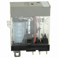
G2R-1-SND-DC12(S)
Description
RELAY SPDT 12VDC PLUG-IN W/LED
Manufacturer
Omron
Series
G2RSr
Datasheets
1.G2R-1A-E-DC12.pdf
(30 pages)
2.G2R-1A-E-DC12.pdf
(14 pages)
3.G2R-1-S_DC12S.pdf
(12 pages)
Specifications of G2R-1-SND-DC12(S)
Relay Type
General Purpose
Contact Form
SPDT (1 Form C)
Contact Rating (current)
10A
Switching Voltage
440VAC, 125VDC - Max
Coil Type
Standard
Coil Current
43.2mA
Coil Voltage
12VDC
Turn On Voltage (max)
8.4 VDC
Turn Off Voltage (min)
1.8 VDC
Mounting Type
Socket
Termination Style
Quick Connect - .187" (4.7mm)
Circuit
SPDT (1 Form C)
Contact Rating @ Voltage
10A @ 250VAC
Control On Voltage (max)
8.4 VDC
Control Off Voltage (min)
1.8 VDC
Coil Voltage Vdc Nom
12V
Contact Current Max
10A
Contact Voltage Ac Nom
250V
Contact Voltage Dc Nom
30V
Coil Resistance
278ohm
Contact Configuration
SPDT
Lead Free Status / RoHS Status
Lead free / RoHS Compliant
Other names
G2R-1-SNDDC12(S)
G2R-1-SNDDC12(S)
G2R1SNDDC12S
Z2952
G2R-1-SNDDC12(S)
G2R1SNDDC12S
Z2952
Available stocks
Company
Part Number
Manufacturer
Quantity
Price
Company:

Part Number:
G2R-1-SND-DC12(S)
Manufacturer:
Omron Electronics Inc-IA Div
Quantity:
135


■ Mounting Position
Depending on where the relay is mounted, the function of the relay
(and the performance of the circuit which includes the relay) may be
adversely affected.
The relay may malfunction if it is mounted near a transformer or other
device that generates a large magnetic field, or much heat. Provide
an adequate distance between the relay and such devices.
Also, keep the relay away from semiconductor devices, if they are to
be mounted on the same PCB.
■ Mounting Direction
To allow a relay to operate to its full capability, adequate consider-
ation must be given to the mounting direction of the relay. Relay char-
acteristics that are considerably influenced by mounting direction are
shock resistance, life expectancy, and contact reliability.
■ Shock Resistance
Ideally, the relay must be mounted so that any shock or vibration is
applied to the relay at right angles to the operating direction of the
armature of the relay. Especially when a relay’s coil is not energized,
the shock resistance and noise immunity are significantly affected by
the mounting direction of the relay.
■ Life Expectancy
When switching a heavy load that generates arc (generally, a load
having a greater impedance than that of the relay coil), substances
spattered from the contact may accumulate in the vicinity, resulting in
degradation of the insulation resistance of the circuit. Mounting the
relay in the correct direction is also important in preventing this kind
of degradation of the insulation resistance.
■ Contact Reliability
Switching both a heavy and a minute load with a single relay contact
is not recommended. The reason for this is that the substances scat-
tered from the contact when the heavy load is switched degrade the
contact when switching the minute load. For example, when using a
multi-pole contact relay, avoid the mounting direction or terminal con-
nections in which the minute load switching contact is located below
the heavy load switching contact.
18
Correct
Incorrect
Electromechanical Relays
Technical Information
■ Mounting Interval
When mounting multiple relays side by side on a PCB, pay attention
to the following points:
When many relays are mounted side by side, they may generate an
abnormally high heat due to the thermal interference between the
relays. Therefore, provide an adequate distance between the relays
to dissipate the heat. When using a relay, be sure to check the mini-
mum mounting interval.
Also, if multiple PCBs with relays are mounted to a rack, the temper-
ature may rise. In this case, preventive measures must be taken so
that the ambient temperature falls within the rated value.
Pattern Layout
Countermeasures Against Noise
The relay can be a noise source when viewed from a semiconductor
circuit. This must be taken into consideration when designing the lay-
out positioning of the relay and other semiconductor components on
the PCB.
• Keep the relay away from semiconductor components as far away
• Locate the surge suppressor for the relay coil as close to the relay
• Do not route wiring for signals such as audio signals that are likely
• Design the shortest possible pattern.
• One method for separating the power source and relay from other
■ Conformal Coating
Coating the PCB is recommended to prevent the circuitry from being
degraded by harmful gases. When coating the PCB, care should be
taken to avoid relay contamination. Otherwise, faulty contact of the
relay may occur due to sticking or coating. Some coating agents may
degrade or adversely affect the relay. Select the coating agent care-
fully.
Epoxy
Urethane
Silicon
as possible.
as possible.
to be affected by noise below the relay.
electronic components is to use shielded patterns.
* Satisfactory for sealed, but totally unsatisfactory for un-
Item
sealed relays.
PCB with relays
Good
Good
Poor *
Applicability to
mounted
Type of Coating
Good insulation. Applying this coat-
ing is a little difficult, but has no effect
on relay contact.
Good insulation and easy to coat. Be
careful not to allow the coating on the
relay itself, as thinner-based solvents
are often used with this coating.
Good insulation and easy to coat.
However, silicon gas may cause con-
tact contamination and misoperation.
Feature
Related parts for G2R-1-SND-DC12(S)
Image
Part Number
Description
Manufacturer
Datasheet
Request
R

Part Number:
Description:
RELAY POWER SPDT 10A 24VDC QCMNT
Manufacturer:
Omron
Datasheet:
Part Number:
Description:
RELAY SPDT 6VDC PLUG-IN W/LED
Manufacturer:
Omron
Datasheet:
Part Number:
Description:
GP Relay
Manufacturer:
Omron
Datasheet:
Part Number:
Description:
RELAY PWR SPDT 10A 12VDC QC MNT
Manufacturer:
Omron
Datasheet:
Part Number:
Description:
RELAY PWR SPDT 10A 24VDC QC MNT
Manufacturer:
Omron
Datasheet:

Part Number:
Description:
POWER RELAY, SPDT, 24VDC, 10A, PLUG IN
Manufacturer:
Omron
Datasheet:

Part Number:
Description:
POWER RELAY, SPDT, 24VDC, 10A, PLUG IN
Manufacturer:
Omron
Datasheet:
Part Number:
Description:
RELAY, SPCO, 10A, 12VDC
Manufacturer:
Omron
Datasheet:

Part Number:
Description:
POWER RELAY, SPDT, 6VDC, 10A, PLUG IN
Manufacturer:
Omron
Datasheet:

Part Number:
Description:
RELAY; E-MECH; POWER; DPDT; CUR-RTG 5A; CTRL-V 24DC; VOL-RTG 250/30AC/DC; SOCKET MNT
Manufacturer:
Omron Automation
Datasheet:

Part Number:
Description:
RELAY GP SPDT 240VAC PLUG-IN
Manufacturer:
Omron
Datasheet:

Part Number:
Description:
Relay
Manufacturer:
Omron
Datasheet: