G2R-1-SND-DC12(S) Omron, G2R-1-SND-DC12(S) Datasheet - Page 4
G2R-1-SND-DC12(S)
Manufacturer Part Number
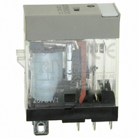
G2R-1-SND-DC12(S)
Description
RELAY SPDT 12VDC PLUG-IN W/LED
Manufacturer
Omron
Series
G2RSr
Datasheets
1.G2R-1A-E-DC12.pdf
(30 pages)
2.G2R-1A-E-DC12.pdf
(14 pages)
3.G2R-1-S_DC12S.pdf
(12 pages)
Specifications of G2R-1-SND-DC12(S)
Relay Type
General Purpose
Contact Form
SPDT (1 Form C)
Contact Rating (current)
10A
Switching Voltage
440VAC, 125VDC - Max
Coil Type
Standard
Coil Current
43.2mA
Coil Voltage
12VDC
Turn On Voltage (max)
8.4 VDC
Turn Off Voltage (min)
1.8 VDC
Mounting Type
Socket
Termination Style
Quick Connect - .187" (4.7mm)
Circuit
SPDT (1 Form C)
Contact Rating @ Voltage
10A @ 250VAC
Control On Voltage (max)
8.4 VDC
Control Off Voltage (min)
1.8 VDC
Coil Voltage Vdc Nom
12V
Contact Current Max
10A
Contact Voltage Ac Nom
250V
Contact Voltage Dc Nom
30V
Coil Resistance
278ohm
Contact Configuration
SPDT
Lead Free Status / RoHS Status
Lead free / RoHS Compliant
Other names
G2R-1-SNDDC12(S)
G2R-1-SNDDC12(S)
G2R1SNDDC12S
Z2952
G2R-1-SNDDC12(S)
G2R1SNDDC12S
Z2952
Available stocks
Company
Part Number
Manufacturer
Quantity
Price
Company:

Part Number:
G2R-1-SND-DC12(S)
Manufacturer:
Omron Electronics Inc-IA Div
Quantity:
135


Terminals
■ Straight PCB Terminals
PCB terminals are normally straight.
Self-clinching (S-shaped) PCB
Terminals
Some relays have terminals that are bent into an “S” shape. This
secures the PCB relay to the PCB prior to soldering, helping the ter-
minals stay in their holes and keeping the relay level.
Dimensions
For miniature relays, the maximum dimensions and the average val-
ues ( ) marked with an asterisk are provided to aid the customer in
designing.
■ Mounting Orientation Mark
On the top of all OMRON relays is a mark indicating where the relay
coil is located. Knowing the coil location aids in designing PCBs
when spacing components. Also, pin orientation is easy to discern
when automatic or hand-mounting relays.
On dimensional drawings in all OMRON literature this mark is left-ori-
ented. Mounting holes, terminal arrangements, and internal connec-
tions follow this alignment. The following two symbols are used to
represent the orientation mark.
4
Detail
Symbol
Example
Drawing
view
Mounting holes
8 max.
(7.9)*
Mark
Electromechanical Relays
3.5
0.3
Mark
Bottom
(Bottom view)
0.4 x 0.4
16 max.
(15.9)*
Terminal
0.6
Terminal arrangement/
internal connections
*Average value
Mark
9.9 max.
(9.8)*
0.25
7.62
Technical Information
(Bottom view)
Top
■ Terminal Arrangement/Internal
Top View
If the terminal arrangement of a relay can be seen from above the
PCB, the top view of the relay is provided in the Dimensions section
of the catalog or data sheet.
Bottom View
If the relay’s terminals cannot be seen from above the PC board, as
in this example, a bottom view is shown.
Rotation Direction to Bottom View
The bottom view shown in the catalog or data sheet is rotated in the
direction indicated by the arrow, with the coil always on the left.
Gull-wing SMT terminal
"Inside L" SMT terminal
Connections
Axis of rotation
Quick-connect
Plug-in
T I O N
terminal
terminal
Related parts for G2R-1-SND-DC12(S)
Image
Part Number
Description
Manufacturer
Datasheet
Request
R

Part Number:
Description:
RELAY POWER SPDT 10A 24VDC QCMNT
Manufacturer:
Omron
Datasheet:
Part Number:
Description:
RELAY SPDT 6VDC PLUG-IN W/LED
Manufacturer:
Omron
Datasheet:
Part Number:
Description:
GP Relay
Manufacturer:
Omron
Datasheet:
Part Number:
Description:
RELAY PWR SPDT 10A 12VDC QC MNT
Manufacturer:
Omron
Datasheet:
Part Number:
Description:
RELAY PWR SPDT 10A 24VDC QC MNT
Manufacturer:
Omron
Datasheet:

Part Number:
Description:
POWER RELAY, SPDT, 24VDC, 10A, PLUG IN
Manufacturer:
Omron
Datasheet:

Part Number:
Description:
POWER RELAY, SPDT, 24VDC, 10A, PLUG IN
Manufacturer:
Omron
Datasheet:
Part Number:
Description:
RELAY, SPCO, 10A, 12VDC
Manufacturer:
Omron
Datasheet:

Part Number:
Description:
POWER RELAY, SPDT, 6VDC, 10A, PLUG IN
Manufacturer:
Omron
Datasheet:

Part Number:
Description:
RELAY; E-MECH; POWER; DPDT; CUR-RTG 5A; CTRL-V 24DC; VOL-RTG 250/30AC/DC; SOCKET MNT
Manufacturer:
Omron Automation
Datasheet:

Part Number:
Description:
RELAY GP SPDT 240VAC PLUG-IN
Manufacturer:
Omron
Datasheet:

Part Number:
Description:
Relay
Manufacturer:
Omron
Datasheet: