G2R-1-SND-DC12(S) Omron, G2R-1-SND-DC12(S) Datasheet - Page 6
G2R-1-SND-DC12(S)
Manufacturer Part Number
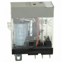
G2R-1-SND-DC12(S)
Description
RELAY SPDT 12VDC PLUG-IN W/LED
Manufacturer
Omron
Series
G2RSr
Datasheets
1.G2R-1A-E-DC12.pdf
(30 pages)
2.G2R-1A-E-DC12.pdf
(14 pages)
3.G2R-1-S_DC12S.pdf
(12 pages)
Specifications of G2R-1-SND-DC12(S)
Relay Type
General Purpose
Contact Form
SPDT (1 Form C)
Contact Rating (current)
10A
Switching Voltage
440VAC, 125VDC - Max
Coil Type
Standard
Coil Current
43.2mA
Coil Voltage
12VDC
Turn On Voltage (max)
8.4 VDC
Turn Off Voltage (min)
1.8 VDC
Mounting Type
Socket
Termination Style
Quick Connect - .187" (4.7mm)
Circuit
SPDT (1 Form C)
Contact Rating @ Voltage
10A @ 250VAC
Control On Voltage (max)
8.4 VDC
Control Off Voltage (min)
1.8 VDC
Coil Voltage Vdc Nom
12V
Contact Current Max
10A
Contact Voltage Ac Nom
250V
Contact Voltage Dc Nom
30V
Coil Resistance
278ohm
Contact Configuration
SPDT
Lead Free Status / RoHS Status
Lead free / RoHS Compliant
Other names
G2R-1-SNDDC12(S)
G2R-1-SNDDC12(S)
G2R1SNDDC12S
Z2952
G2R-1-SNDDC12(S)
G2R1SNDDC12S
Z2952
Available stocks
Company
Part Number
Manufacturer
Quantity
Price
Company:

Part Number:
G2R-1-SND-DC12(S)
Manufacturer:
Omron Electronics Inc-IA Div
Quantity:
135


Glossary
■ Terms Related to Contacts
Carry Current
The value of the current which can be continuously applied to the
relay contacts without opening or closing them, and which allows the
relay to stay within the permissible temperature rise.
Maximum Switching Current
A current which serves as a reference in determining the perfor-
mance of the relay contacts. This value will never exceed the current
flow. When using a relay, do not exceed this value.
Contact Form
OMRON uses the following relay terminology for the various polarity
and switch configurations.
1 FORM A: SPST-NO
1 FORM B: SPST-NC
1 FORM C: SPDT
2 FORM C: DPDT
Make-before-break (MBB) Contact
A contact arrangement in which part of the switching section is
shared between both an NO and NC contact. When the relay oper-
ates or releases, the contact that closes the circuit operates before
the contact that opens the circuit releases. Thus both contacts are
closed momentarily at the same time.
6
Contact symbols
Double-break
Make-before-break
NO
Electromechanical Relays
NC
Latching relays
NC
DT
Technical Information
Contact Resistance
The total resistance of the conductor, as well as specific resistivities
such as of the armature and terminal, and the resistance of the con-
tacts. Contact resistance values given in this catalog are initial val-
ues. These values are not intended to indicate suitability or
unsuitability in actual use. The contact resistance values given are
measurement values for a stable contact circuit at a stable contact
resistance. This value is determined by measuring the voltage drop
across the contacts by applying test currents as shown in the table
below.
For most applications, use at least 1 A, 5 VDC for contact resistance
measurements.
Maximum Switching Capacity
The maximum value of the load capacity which can be switched with-
out problem. When using a relay, do not exceed this value.
For example, when maximum switching voltage V
mum switching current I
on the characteristic curve “Maximum Switching Capacity” shown
below. Conversely, maximum switching voltage V
I
Under 0.01
0.01 to 0.1
0.1 to 1
Over 1
1
is known.
Maximum switching current (I
Maximum switching voltage (V
For instance, if the maximum switching voltage = 40 V
Maximum switching current = 2 A (see circled point on graph
below.)
Rated current (A)
1
can be obtained at the point of intersection
Switching voltage (V)
1
) =
1
) =
1
10
100
1000
Max. switching power [W(VA)]
Max. switching power [W(VA)]
Max. switching voltage (V1)
Max. switching current (I1)
Test current (mA)
1
can be obtained if
1
is known, maxi-
Related parts for G2R-1-SND-DC12(S)
Image
Part Number
Description
Manufacturer
Datasheet
Request
R

Part Number:
Description:
RELAY POWER SPDT 10A 24VDC QCMNT
Manufacturer:
Omron
Datasheet:
Part Number:
Description:
RELAY SPDT 6VDC PLUG-IN W/LED
Manufacturer:
Omron
Datasheet:
Part Number:
Description:
GP Relay
Manufacturer:
Omron
Datasheet:
Part Number:
Description:
RELAY PWR SPDT 10A 12VDC QC MNT
Manufacturer:
Omron
Datasheet:
Part Number:
Description:
RELAY PWR SPDT 10A 24VDC QC MNT
Manufacturer:
Omron
Datasheet:

Part Number:
Description:
POWER RELAY, SPDT, 24VDC, 10A, PLUG IN
Manufacturer:
Omron
Datasheet:

Part Number:
Description:
POWER RELAY, SPDT, 24VDC, 10A, PLUG IN
Manufacturer:
Omron
Datasheet:
Part Number:
Description:
RELAY, SPCO, 10A, 12VDC
Manufacturer:
Omron
Datasheet:

Part Number:
Description:
POWER RELAY, SPDT, 6VDC, 10A, PLUG IN
Manufacturer:
Omron
Datasheet:

Part Number:
Description:
RELAY; E-MECH; POWER; DPDT; CUR-RTG 5A; CTRL-V 24DC; VOL-RTG 250/30AC/DC; SOCKET MNT
Manufacturer:
Omron Automation
Datasheet:

Part Number:
Description:
RELAY GP SPDT 240VAC PLUG-IN
Manufacturer:
Omron
Datasheet:

Part Number:
Description:
Relay
Manufacturer:
Omron
Datasheet: