G2R-1-SND-DC12(S) Omron, G2R-1-SND-DC12(S) Datasheet - Page 26
G2R-1-SND-DC12(S)
Manufacturer Part Number
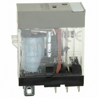
G2R-1-SND-DC12(S)
Description
RELAY SPDT 12VDC PLUG-IN W/LED
Manufacturer
Omron
Series
G2RSr
Datasheets
1.G2R-1A-E-DC12.pdf
(30 pages)
2.G2R-1A-E-DC12.pdf
(14 pages)
3.G2R-1-S_DC12S.pdf
(12 pages)
Specifications of G2R-1-SND-DC12(S)
Relay Type
General Purpose
Contact Form
SPDT (1 Form C)
Contact Rating (current)
10A
Switching Voltage
440VAC, 125VDC - Max
Coil Type
Standard
Coil Current
43.2mA
Coil Voltage
12VDC
Turn On Voltage (max)
8.4 VDC
Turn Off Voltage (min)
1.8 VDC
Mounting Type
Socket
Termination Style
Quick Connect - .187" (4.7mm)
Circuit
SPDT (1 Form C)
Contact Rating @ Voltage
10A @ 250VAC
Control On Voltage (max)
8.4 VDC
Control Off Voltage (min)
1.8 VDC
Coil Voltage Vdc Nom
12V
Contact Current Max
10A
Contact Voltage Ac Nom
250V
Contact Voltage Dc Nom
30V
Coil Resistance
278ohm
Contact Configuration
SPDT
Lead Free Status / RoHS Status
Lead free / RoHS Compliant
Other names
G2R-1-SNDDC12(S)
G2R-1-SNDDC12(S)
G2R1SNDDC12S
Z2952
G2R-1-SNDDC12(S)
G2R1SNDDC12S
Z2952
Available stocks
Company
Part Number
Manufacturer
Quantity
Price
Company:

Part Number:
G2R-1-SND-DC12(S)
Manufacturer:
Omron Electronics Inc-IA Div
Quantity:
135


■ Countermeasures Against
If a load such as a capacitor or lamp through which an inrush current
flows is connected to the power source and contact of the relay, the
supply voltage may drop when the contact is closed, causing the
relay to abnormally release.
Increasing the capacity of the transformer or providing an additional
control circuit can be used to prevent this drop in the supply voltage.
On some occasions, use of the following circuit may prevent voltage
drop.
The same circuit also applies when the relay is driven by a battery.
■ Designing Power-Conserving
This section introduces a patented drive circuit for the single-winding
latching relay that can be driven on several milliwatts. This drive cir-
cuit not only allows the relay to be used in the same manner as semi-
conductor devices but also offers a wide range of applications.
Operating principle
Set
When a specified voltage is applied across E, the current flows
through the circuit in the sequence of diode Di1, capacitor C, relay
Ry, and diode Di2. C is then charged, setting the relay.
26
Inrush Current
Driver Circuit with Single-
Winding Latching Relay
Electromechanical Relays
Technical Information
Energization
When C has been fully charged, the relay is biased by the current
flowing from Di1 to Rb. C does not discharge. The power consump-
tion at this time is very small, several milliwatts at best, and its value
can be calculated as follows:
P =
where,
P: power consumption
V
The current that is to flow through Rb at this time is dependent on the
transfer ratio h
Reset
When the voltage placed across E is removed, the electricity charged
in C is discharged, causing the current to flow through the circuit in
the sequence of Rb, the base, and the emitter of TR. In this way, the
relay is reset by the current flowing in the direction opposite to when
the relay is set.
The following equivalent circuits respectively illustrate the current
flows when the relay is set, energized, and reset.
Set
Energization
Reset
Circuit design
Fundamental
Generally, the latching relay is set and reset when a pulse having a
square waveform is applied to it for a short time. The minimum pulse
width required to set and reset the relay is predetermined.
The charging current shown in the above equivalent circuit diagrams,
has a sawtooth waveform that can be expressed by the following for-
mula, because it is the primary circuit of C and R.
(2 Forward voltage diode drops)
F
: voltage drop across diode Di1
(
------------------------ -
E V
–
Rb
F
)
2
fe
of transistor TR which is required for TR to turn ON.
Related parts for G2R-1-SND-DC12(S)
Image
Part Number
Description
Manufacturer
Datasheet
Request
R

Part Number:
Description:
RELAY POWER SPDT 10A 24VDC QCMNT
Manufacturer:
Omron
Datasheet:
Part Number:
Description:
RELAY SPDT 6VDC PLUG-IN W/LED
Manufacturer:
Omron
Datasheet:
Part Number:
Description:
GP Relay
Manufacturer:
Omron
Datasheet:
Part Number:
Description:
RELAY PWR SPDT 10A 12VDC QC MNT
Manufacturer:
Omron
Datasheet:
Part Number:
Description:
RELAY PWR SPDT 10A 24VDC QC MNT
Manufacturer:
Omron
Datasheet:

Part Number:
Description:
POWER RELAY, SPDT, 24VDC, 10A, PLUG IN
Manufacturer:
Omron
Datasheet:

Part Number:
Description:
POWER RELAY, SPDT, 24VDC, 10A, PLUG IN
Manufacturer:
Omron
Datasheet:
Part Number:
Description:
RELAY, SPCO, 10A, 12VDC
Manufacturer:
Omron
Datasheet:

Part Number:
Description:
POWER RELAY, SPDT, 6VDC, 10A, PLUG IN
Manufacturer:
Omron
Datasheet:

Part Number:
Description:
RELAY; E-MECH; POWER; DPDT; CUR-RTG 5A; CTRL-V 24DC; VOL-RTG 250/30AC/DC; SOCKET MNT
Manufacturer:
Omron Automation
Datasheet:

Part Number:
Description:
RELAY GP SPDT 240VAC PLUG-IN
Manufacturer:
Omron
Datasheet:

Part Number:
Description:
Relay
Manufacturer:
Omron
Datasheet: