G2R-1-SND-DC12(S) Omron, G2R-1-SND-DC12(S) Datasheet - Page 14
G2R-1-SND-DC12(S)
Manufacturer Part Number
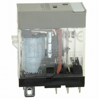
G2R-1-SND-DC12(S)
Description
RELAY SPDT 12VDC PLUG-IN W/LED
Manufacturer
Omron
Series
G2RSr
Datasheets
1.G2R-1A-E-DC12.pdf
(30 pages)
2.G2R-1A-E-DC12.pdf
(14 pages)
3.G2R-1-S_DC12S.pdf
(12 pages)
Specifications of G2R-1-SND-DC12(S)
Relay Type
General Purpose
Contact Form
SPDT (1 Form C)
Contact Rating (current)
10A
Switching Voltage
440VAC, 125VDC - Max
Coil Type
Standard
Coil Current
43.2mA
Coil Voltage
12VDC
Turn On Voltage (max)
8.4 VDC
Turn Off Voltage (min)
1.8 VDC
Mounting Type
Socket
Termination Style
Quick Connect - .187" (4.7mm)
Circuit
SPDT (1 Form C)
Contact Rating @ Voltage
10A @ 250VAC
Control On Voltage (max)
8.4 VDC
Control Off Voltage (min)
1.8 VDC
Coil Voltage Vdc Nom
12V
Contact Current Max
10A
Contact Voltage Ac Nom
250V
Contact Voltage Dc Nom
30V
Coil Resistance
278ohm
Contact Configuration
SPDT
Lead Free Status / RoHS Status
Lead free / RoHS Compliant
Other names
G2R-1-SNDDC12(S)
G2R-1-SNDDC12(S)
G2R1SNDDC12S
Z2952
G2R-1-SNDDC12(S)
G2R1SNDDC12S
Z2952
Available stocks
Company
Part Number
Manufacturer
Quantity
Price
Company:

Part Number:
G2R-1-SND-DC12(S)
Manufacturer:
Omron Electronics Inc-IA Div
Quantity:
135


Contact Protection Circuit
A contact protection circuit, designed to prolong the life of the relay, is recommended. This protection will have the additional advantages of sup-
pressing noise, as well as preventing the generation of carbide and nitric acid, which otherwise would be generated at the contact surface when
the relay contact is opened. However, unless designed correctly, the protection circuit may produce adverse effects, such as prolonging the release
time of the relay. The following table lists examples of contact protection circuits.
Avoid use of a surge suppressor in the manner shown below.
Although it is considered that switching a DC inductive load is more difficult than a resistive load, an appropriate contact protection circuit can
achieve almost the same characteristics.
14
CR
Diode
Diode +
Zener
Diode
Varistor
This circuit arrangement is very effective for diminishing sparking (arc-
ing) at the contacts, when breaking the circuit. However, since electrical
energy is stored in C (capacitor) when the contacts are open, the current
from C flows into the contacts when they close. Therefore, metal degra-
dation is likely to occur between mating contacts due to capacitive
current inrush.
Circuit example
Electromechanical Relays
Power
source
Power
source
Power
source
Power
source
Power
source
Power
supply
Inductive
load
Inductive
load
Inductive
load
Inductive
load
Inductive
load
Load
Fair
Good
N/A
N/A
Good
Technical Information
AC
Applicability
Good
Good
Good
Good
Good
DC
This circuit is effective if connected
The diode protects the coil and driver
Load impedance must be much small-
er than the RC circuit when the relay
operates on an AC voltage.
across the load when the supply volt-
age is 24 to 48 V. When the supply
voltage is 100 to 240 V, connect the
circuit across the contacts.
circuit from inductive kickback. Relays
with a diode connected in parallel with
the relay coil tend to experience in-
creased release times.
This circuit effectively shortens re-
lease time in applications where the
release time of a diode protection cir-
cuit proves to be too slow.
By utilizing the constant-voltage char-
acteristic of a varistor, this circuit pre-
vents high voltages from being
applied across the contacts. This cir-
cuit also somewhat delays the release
time. This circuit, if connected across
the load, is effective when the supply
voltage is 24 to 48 V. If the supply volt-
age is 100 to 240 V, connect the circuit
across the contacts.
This circuit arrangement is very useful for diminishing sparking (arcing)
at the contacts when breaking the circuit. However, since the charging
current to C flows into the contacts when they are closed, metal degra-
dation is likely to occur between the mating contacts due to capacitive
current inrush.
Features and remarks
Power
supply
Optimum C and R values are:
C: 1 to 0.5 μF for 1–A switching cur-
rent R: 0.5 to 1Ω for 1–V switching
voltage
These values do not always agree
with the optimum values due to the
nature of the load and the dispersion
in the relay characteristics. Confirm
optimum values experimentally. Ca-
pacitor C suppresses discharge when
the contacts are opened, while resis-
tor R limits the current applied when
the contacts are closed the next time.
Generally, employ a capacitor C
whose dielectric strength is 200 to
300 V, or more than double the switch-
ing voltage. If the circuit is powered by
an AC power source, employ an AC
capacitor (non-polarized).
Employ a diode having a reverse
breakdown voltage of more than
10 times the circuit voltage and a for-
ward current rating greater than the
load current. A diode having a reverse
breakdown voltage two to three times
that of the supply voltage can be used
in an electronic circuit where the cir-
cuit voltage is not particularly high.
The zener diode breakdown voltage
should be about the same as the sup-
ply voltage.
—
Load
Element selection
Related parts for G2R-1-SND-DC12(S)
Image
Part Number
Description
Manufacturer
Datasheet
Request
R

Part Number:
Description:
RELAY POWER SPDT 10A 24VDC QCMNT
Manufacturer:
Omron
Datasheet:
Part Number:
Description:
RELAY SPDT 6VDC PLUG-IN W/LED
Manufacturer:
Omron
Datasheet:
Part Number:
Description:
GP Relay
Manufacturer:
Omron
Datasheet:
Part Number:
Description:
RELAY PWR SPDT 10A 12VDC QC MNT
Manufacturer:
Omron
Datasheet:
Part Number:
Description:
RELAY PWR SPDT 10A 24VDC QC MNT
Manufacturer:
Omron
Datasheet:

Part Number:
Description:
POWER RELAY, SPDT, 24VDC, 10A, PLUG IN
Manufacturer:
Omron
Datasheet:

Part Number:
Description:
POWER RELAY, SPDT, 24VDC, 10A, PLUG IN
Manufacturer:
Omron
Datasheet:
Part Number:
Description:
RELAY, SPCO, 10A, 12VDC
Manufacturer:
Omron
Datasheet:

Part Number:
Description:
POWER RELAY, SPDT, 6VDC, 10A, PLUG IN
Manufacturer:
Omron
Datasheet:

Part Number:
Description:
RELAY; E-MECH; POWER; DPDT; CUR-RTG 5A; CTRL-V 24DC; VOL-RTG 250/30AC/DC; SOCKET MNT
Manufacturer:
Omron Automation
Datasheet:

Part Number:
Description:
RELAY GP SPDT 240VAC PLUG-IN
Manufacturer:
Omron
Datasheet:

Part Number:
Description:
Relay
Manufacturer:
Omron
Datasheet: