G2R-1-SND-DC12(S) Omron, G2R-1-SND-DC12(S) Datasheet - Page 23
G2R-1-SND-DC12(S)
Manufacturer Part Number
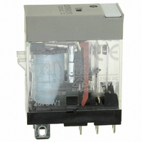
G2R-1-SND-DC12(S)
Description
RELAY SPDT 12VDC PLUG-IN W/LED
Manufacturer
Omron
Series
G2RSr
Datasheets
1.G2R-1A-E-DC12.pdf
(30 pages)
2.G2R-1A-E-DC12.pdf
(14 pages)
3.G2R-1-S_DC12S.pdf
(12 pages)
Specifications of G2R-1-SND-DC12(S)
Relay Type
General Purpose
Contact Form
SPDT (1 Form C)
Contact Rating (current)
10A
Switching Voltage
440VAC, 125VDC - Max
Coil Type
Standard
Coil Current
43.2mA
Coil Voltage
12VDC
Turn On Voltage (max)
8.4 VDC
Turn Off Voltage (min)
1.8 VDC
Mounting Type
Socket
Termination Style
Quick Connect - .187" (4.7mm)
Circuit
SPDT (1 Form C)
Contact Rating @ Voltage
10A @ 250VAC
Control On Voltage (max)
8.4 VDC
Control Off Voltage (min)
1.8 VDC
Coil Voltage Vdc Nom
12V
Contact Current Max
10A
Contact Voltage Ac Nom
250V
Contact Voltage Dc Nom
30V
Coil Resistance
278ohm
Contact Configuration
SPDT
Lead Free Status / RoHS Status
Lead free / RoHS Compliant
Other names
G2R-1-SNDDC12(S)
G2R-1-SNDDC12(S)
G2R1SNDDC12S
Z2952
G2R-1-SNDDC12(S)
G2R1SNDDC12S
Z2952
Available stocks
Company
Part Number
Manufacturer
Quantity
Price
Company:

Part Number:
G2R-1-SND-DC12(S)
Manufacturer:
Omron Electronics Inc-IA Div
Quantity:
135


I
7. Using the following formula, calculate the power dissipated by the
Total power dissipation vs. ambient temperature
In case the total dissipation exceeds the permissible power dissipa-
tion, either attach a radiator plate to the transistor, or replace the
transistor.
8. Determine the supply voltage to the relay.
C
vs. V
transistor to confirm that it is within the range of permissible
power dissipation of the transistor.
Total power dissipation P
pation P
P
(V
P
(For details on l
Confirm that P
representing the total power dissipation vs. ambient temperature
characteristics.
The maximum and minimum values of the supply voltage to the
relay are determined by the following expressions using the
upper- and lower-limit values of the pickup voltage V
step 6.
Maximum supply voltage ≤ Upperlimit pickup voltage + V
Minimum supply voltage ≥ Lowerlimit pickup voltage + V
C
B
CE
= Maximum value of pickup voltage/ Coil resistance x V
= l
is determined in step 6.)
CE
B
x 0.6 to 1
characteristics (Example)
B
where,
T
B
obtained by the above formula is within the curve
, refer to step 6.)
T
= Collector dissipation P
Electromechanical Relays
C
CE
+ Base dissi-
obtained in
CE
CE
CE
9. Verify that the following conditions are satisfied.
10.Check the following items during actual use of the relay.
From the above discussion, the best relay coil should be rated at
12 VDC or 24 VDC when the relay is driven by a transistor.
■ Driving by Darlington-
To reduce the current of the transistor to drive the relay (i.e., base
current of the transistor), two transistors may be used, via Darlington
connection. Darlington connected transistors are available enclosed
in a single package.
NPN-NPN Darlington Connection
When the Darlington-connected transistors are used, the required
value of V
reason, consideration must be given to designing the total power dis-
sipation and supply voltage for the second transistor, Tr2.
Rated voltage of relay
Coil current*
I
V
Driving current of transistor
Voltage drop V
Voltage dropV
Total power dissipation P
C
* Determine the safety factor giving consideration to external
* Inversely proportional to voltage
** Often used V
ECO
of switching transistor
V
V
• Is the upper-limit value of the pickup voltage equal to or less
• Is the lower-limit value of the pickup voltage equal to or more
• Are the above conditions satisfied within the operating tempera-
• Is there any abnormality found in a test run?
In addition to checking the above items, take into consideration
the items listed in this table.
Connected Transistors
CEO
CBO
surge (such as lightning and surge from other devices).
than the rated value when the maximum supply voltage is
applied?
than the rated value when the minimum supply voltage is
applied?
ture range?
, V
CEO
> (Maximum supply voltage + surge voltage) x safety factor*
> (Maximum supply voltage + surge voltage) x safety factor*
CE
of switching transistor**
Technical Information
is higher than when using a single transistor. For this
BE
CE
in transistor
in transistor
CEO
: 35 to 60 V
T
of transistor
Low
High
High
Low
High
High
High
High
High
Low
Low
High
Low
Low
Low
Low
23
Related parts for G2R-1-SND-DC12(S)
Image
Part Number
Description
Manufacturer
Datasheet
Request
R

Part Number:
Description:
RELAY POWER SPDT 10A 24VDC QCMNT
Manufacturer:
Omron
Datasheet:
Part Number:
Description:
RELAY SPDT 6VDC PLUG-IN W/LED
Manufacturer:
Omron
Datasheet:
Part Number:
Description:
GP Relay
Manufacturer:
Omron
Datasheet:
Part Number:
Description:
RELAY PWR SPDT 10A 12VDC QC MNT
Manufacturer:
Omron
Datasheet:
Part Number:
Description:
RELAY PWR SPDT 10A 24VDC QC MNT
Manufacturer:
Omron
Datasheet:

Part Number:
Description:
POWER RELAY, SPDT, 24VDC, 10A, PLUG IN
Manufacturer:
Omron
Datasheet:

Part Number:
Description:
POWER RELAY, SPDT, 24VDC, 10A, PLUG IN
Manufacturer:
Omron
Datasheet:
Part Number:
Description:
RELAY, SPCO, 10A, 12VDC
Manufacturer:
Omron
Datasheet:

Part Number:
Description:
POWER RELAY, SPDT, 6VDC, 10A, PLUG IN
Manufacturer:
Omron
Datasheet:

Part Number:
Description:
RELAY; E-MECH; POWER; DPDT; CUR-RTG 5A; CTRL-V 24DC; VOL-RTG 250/30AC/DC; SOCKET MNT
Manufacturer:
Omron Automation
Datasheet:

Part Number:
Description:
RELAY GP SPDT 240VAC PLUG-IN
Manufacturer:
Omron
Datasheet:

Part Number:
Description:
Relay
Manufacturer:
Omron
Datasheet: