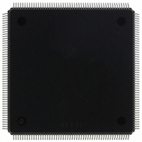
MCF5407AI220 Freescale Semiconductor, MCF5407AI220 Datasheet - Page 377

MCF5407AI220
Manufacturer Part Number
MCF5407AI220
Description
IC MPU 32B 220MHZ COLDF 208-FQFP
Manufacturer
Freescale Semiconductor
Series
MCF540xr
Specifications of MCF5407AI220
Core Processor
Coldfire V4
Core Size
32-Bit
Speed
220MHz
Connectivity
EBI/EMI, I²C, UART/USART
Peripherals
DMA, WDT
Number Of I /o
16
Program Memory Type
ROMless
Ram Size
4K x 8
Voltage - Supply (vcc/vdd)
1.65 V ~ 3.6 V
Oscillator Type
External
Operating Temperature
0°C ~ 70°C
Package / Case
208-FQFP
Maximum Clock Frequency
220 MHz
Operating Supply Voltage
1.8 V, 3.3 V
Maximum Operating Temperature
+ 105 C
Mounting Style
SMD/SMT
Minimum Operating Temperature
0 C
Program Memory Size
24KB
Cpu Speed
220MHz
Embedded Interface Type
I2C, UART
Digital Ic Case Style
FQFP
No. Of Pins
208
Supply Voltage Range
3.3V
Rohs Compliant
Yes
For Use With
M5407C3 - KIT EVAL FOR MCF5407 W/ETHERNET
Lead Free Status / RoHS Status
Lead free / RoHS Compliant
Eeprom Size
-
Program Memory Size
-
Data Converters
-
Lead Free Status / Rohs Status
Lead free / RoHS Compliant
Available stocks
Company
Part Number
Manufacturer
Quantity
Price
Company:
Part Number:
MCF5407AI220
Manufacturer:
freescaie
Quantity:
6
Company:
Part Number:
MCF5407AI220
Manufacturer:
Freescale Semiconductor
Quantity:
135
Company:
Part Number:
MCF5407AI220
Manufacturer:
FREESCALE
Quantity:
1 831
Company:
Part Number:
MCF5407AI220
Manufacturer:
Freescale Semiconductor
Quantity:
10 000
- Current page: 377 of 546
- Download datasheet (7Mb)
Features of this local loop-back mode are as follows:
14.5.3.3 Remote Loop-Back Mode
In remote loop-back mode, shown in Figure 14-37, the channel automatically transmits
received data bit by bit on the TxD output. The local CPU-to-transmitter link is disabled.
This mode is useful in testing receiver and transmitter operation of a remote channel. For
this mode, the transmitter uses the receiver clock.
Because the receiver is not active, received data cannot be read by the CPU and error status
conditions are inactive. Received parity is not checked and is not recalculated for
transmission. Stop bits are sent as they are received. A received break is echoed as received
until the next valid start bit is detected.
14.5.4 Multidrop Mode
Setting UMR1n[PM] programs the UART to operate in a wake-up mode for multidrop or
multiprocessor applications. In this mode, a master can transmit an address character
followed by a block of data characters targeted for one of up to 256 slave stations.
Although slave stations have their channel receivers disabled, they continuously monitor
the master’s data stream. When the master sends an address character, the slave receiver
channel notifies its respective CPU by setting USRn[RxRDY] and generating an interrupt
(if programmed to do so). Each slave station CPU then compares the received address to its
station address and enables its receiver if it wishes to receive the subsequent data characters
or block of data from the master station. Slave stations not addressed continue monitoring
the data stream. Data fields in the data stream are separated by an address character. After
a slave receives a block of data, its CPU disables the receiver and repeats the process.
• Transmitter and CPU-to-receiver communications continue normally in this mode.
• RxD input data is ignored
• TxD is held marking
• The receiver is clocked by the transmitter clock. The transmitter must be enabled,
but the receiver need not be.
CPU
Figure 14-37. Remote Loop-Back
Disabled
Disabled
Chapter 14. UART Modules
Rx
Tx
Disabled
Disabled
RxD Input
TxD Input
Operation
14-35
Related parts for MCF5407AI220
Image
Part Number
Description
Manufacturer
Datasheet
Request
R
Part Number:
Description:
Mcf5407 Coldfire Integrated Microprocessor User
Manufacturer:
Freescale Semiconductor, Inc
Datasheet:
Part Number:
Description:
Manufacturer:
Freescale Semiconductor, Inc
Datasheet:
Part Number:
Description:
Manufacturer:
Freescale Semiconductor, Inc
Datasheet:
Part Number:
Description:
Manufacturer:
Freescale Semiconductor, Inc
Datasheet:
Part Number:
Description:
Manufacturer:
Freescale Semiconductor, Inc
Datasheet:
Part Number:
Description:
Manufacturer:
Freescale Semiconductor, Inc
Datasheet:
Part Number:
Description:
Manufacturer:
Freescale Semiconductor, Inc
Datasheet:
Part Number:
Description:
Manufacturer:
Freescale Semiconductor, Inc
Datasheet:
Part Number:
Description:
Manufacturer:
Freescale Semiconductor, Inc
Datasheet:
Part Number:
Description:
Manufacturer:
Freescale Semiconductor, Inc
Datasheet:
Part Number:
Description:
Manufacturer:
Freescale Semiconductor, Inc
Datasheet:
Part Number:
Description:
Manufacturer:
Freescale Semiconductor, Inc
Datasheet:
Part Number:
Description:
Manufacturer:
Freescale Semiconductor, Inc
Datasheet:
Part Number:
Description:
Manufacturer:
Freescale Semiconductor, Inc
Datasheet:
Part Number:
Description:
Manufacturer:
Freescale Semiconductor, Inc
Datasheet:


