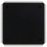
MCF5407AI220 Freescale Semiconductor, MCF5407AI220 Datasheet - Page 516

MCF5407AI220
Manufacturer Part Number
MCF5407AI220
Description
IC MPU 32B 220MHZ COLDF 208-FQFP
Manufacturer
Freescale Semiconductor
Series
MCF540xr
Specifications of MCF5407AI220
Core Processor
Coldfire V4
Core Size
32-Bit
Speed
220MHz
Connectivity
EBI/EMI, I²C, UART/USART
Peripherals
DMA, WDT
Number Of I /o
16
Program Memory Type
ROMless
Ram Size
4K x 8
Voltage - Supply (vcc/vdd)
1.65 V ~ 3.6 V
Oscillator Type
External
Operating Temperature
0°C ~ 70°C
Package / Case
208-FQFP
Maximum Clock Frequency
220 MHz
Operating Supply Voltage
1.8 V, 3.3 V
Maximum Operating Temperature
+ 105 C
Mounting Style
SMD/SMT
Minimum Operating Temperature
0 C
Program Memory Size
24KB
Cpu Speed
220MHz
Embedded Interface Type
I2C, UART
Digital Ic Case Style
FQFP
No. Of Pins
208
Supply Voltage Range
3.3V
Rohs Compliant
Yes
For Use With
M5407C3 - KIT EVAL FOR MCF5407 W/ETHERNET
Lead Free Status / RoHS Status
Lead free / RoHS Compliant
Eeprom Size
-
Program Memory Size
-
Data Converters
-
Lead Free Status / Rohs Status
Lead free / RoHS Compliant
Available stocks
Company
Part Number
Manufacturer
Quantity
Price
Company:
Part Number:
MCF5407AI220
Manufacturer:
freescaie
Quantity:
6
Company:
Part Number:
MCF5407AI220
Manufacturer:
Freescale Semiconductor
Quantity:
135
Company:
Part Number:
MCF5407AI220
Manufacturer:
FREESCALE
Quantity:
1 831
Company:
Part Number:
MCF5407AI220
Manufacturer:
Freescale Semiconductor
Quantity:
10 000
- Current page: 516 of 546
- Download datasheet (7Mb)
Revision C Debug
Command complete status (0x0FFFF) is returned when register write is complete.
A.8.3 Debug Programming Model
In addition to existing BDM commands that provide access to the processor’s registers and
the memory subsystem, the debug module contains a number of registers to support the
required functionality. These registers are treated as 32-bit quantities, regardless of the
number of bits in the implementation. The debug control registers (DRc) are addressed
using a 5-bit value as part of two new BDM commands (
and
). These values
WDREG
RDREG
are shown in Table A-11.
These registers are also accessible from the processor’s supervisor programming model
through the execution of the WDEBUG instruction. Thus, the breakpoint hardware within
the debug module can be accessed by the external development system using the serial
interface or by the operating system running on the processor core. It is the software’s
responsibility to guarantee that all accesses to these resources are serialized and are
logically consistent. The hardware provides a locking mechanism in the CSR to allow the
external development system to disable any attempted writes by the processor to the
breakpoint registers (setting IPW).
The following sections describe the newly added breakpoint registers in Debug C.
A.8.3.1 Address Breakpoint 1 Registers (ABLR1, ABHR1)
The 32-bit address breakpoint 1 registers define an upper (ABHR1) and a lower (ABLR1)
boundary for a region in the operand logical address space of the processor that can be used
as part of the trigger. The ABLR1 and ABHR1 values are compared with the ColdFire CPU
core address signals, as defined by the setting of the trigger definition register (TDR) and
the extended trigger definition register (XTDR).
A.8.3.2 Address Attribute Breakpoint Register 1 (AATR1)
The address attribute breakpoint register 1 (AATR1) defines the address attributes and a
mask associated with ABLR1 and ABHR1 to be matched in the trigger. The AATR1 value
is compared with the ColdFire CPU core address attribute signals, as defined by the setting
of the TDR and XTDR. The format of the AATR1 is the same as the AATR register. For
more details about these registers see Section 5.4.1, “Address Attribute Trigger Registers
(AATR, AATR1)”.
A.8.3.3 Program Counter Breakpoint Registers 1–3 (PBR1–PBR3)
Each of the program counter (PC) breakpoint registers (PBR, PBR1–PBR3) defines an
instruction address that can be used as part of the trigger. PBRn registers are compared with
the processor’s program counter register when the appropriate valid bit is asserted and TDR
is configured appropriately. For more details about these registers see Section 5.4.6,
“Program Counter Breakpoint/Mask Registers (PBR, PBR1, PBR2, PBR3, PBMR)”.
MCF5407 User’s Manual
A-14
Related parts for MCF5407AI220
Image
Part Number
Description
Manufacturer
Datasheet
Request
R
Part Number:
Description:
Mcf5407 Coldfire Integrated Microprocessor User
Manufacturer:
Freescale Semiconductor, Inc
Datasheet:
Part Number:
Description:
Manufacturer:
Freescale Semiconductor, Inc
Datasheet:
Part Number:
Description:
Manufacturer:
Freescale Semiconductor, Inc
Datasheet:
Part Number:
Description:
Manufacturer:
Freescale Semiconductor, Inc
Datasheet:
Part Number:
Description:
Manufacturer:
Freescale Semiconductor, Inc
Datasheet:
Part Number:
Description:
Manufacturer:
Freescale Semiconductor, Inc
Datasheet:
Part Number:
Description:
Manufacturer:
Freescale Semiconductor, Inc
Datasheet:
Part Number:
Description:
Manufacturer:
Freescale Semiconductor, Inc
Datasheet:
Part Number:
Description:
Manufacturer:
Freescale Semiconductor, Inc
Datasheet:
Part Number:
Description:
Manufacturer:
Freescale Semiconductor, Inc
Datasheet:
Part Number:
Description:
Manufacturer:
Freescale Semiconductor, Inc
Datasheet:
Part Number:
Description:
Manufacturer:
Freescale Semiconductor, Inc
Datasheet:
Part Number:
Description:
Manufacturer:
Freescale Semiconductor, Inc
Datasheet:
Part Number:
Description:
Manufacturer:
Freescale Semiconductor, Inc
Datasheet:
Part Number:
Description:
Manufacturer:
Freescale Semiconductor, Inc
Datasheet:


