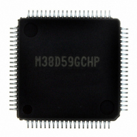
M38D59GCHP#U0 Renesas Electronics America, M38D59GCHP#U0 Datasheet - Page 98

M38D59GCHP#U0
Manufacturer Part Number
M38D59GCHP#U0
Description
IC 740/38D5 MCU QZ-ROM 80LQFP
Manufacturer
Renesas Electronics America
Series
740/38000r
Datasheet
1.M38D58G8FPU0.pdf
(144 pages)
Specifications of M38D59GCHP#U0
Core Processor
740
Core Size
8-Bit
Speed
12.5MHz
Connectivity
SIO, UART/USART
Peripherals
LCD, LED, PWM, WDT
Number Of I /o
59
Program Memory Size
48KB (48K x 8)
Program Memory Type
QzROM
Ram Size
2K x 8
Voltage - Supply (vcc/vdd)
1.8 V ~ 5.5 V
Data Converters
A/D 8x10b
Oscillator Type
Internal
Operating Temperature
-20°C ~ 85°C
Package / Case
80-LQFP
Lead Free Status / RoHS Status
Lead free / RoHS Compliant
Eeprom Size
-
Available stocks
Company
Part Number
Manufacturer
Quantity
Price
38D5 Group
Rev.3.04
REJ03B0158-0304
Countermeasures against noise
(1) Shortest wiring length
1. Wiring for RESET pin
• Reason
The width of a pulse input into the RESET pin is determined by
the timing necessary conditions. If noise having a shorter pulse
width than the standard is input to the RESET pin, the reset is
released before the internal state of the microcomputer is
completely initialized. This may cause a program runaway.
Fig. 91 Wiring for the RESET pin
2. Wiring for clock input/output pins
• Reason
If noise enters clock I/O pins, clock waveforms may be
deformed.
This may cause a program failure or program runaway. Also, if a
potential difference is caused by the noise between the V
of a microcomputer and the V
clock will not be input in the microcomputer.
Make the length of wiring which is connected to the RESET
pin as short as possible. Especially, connect a capacitor across
the RESET pin and the V
wiring (within 20 mm).
• Make the length of wiring which is connected to clock I/O
• Make the length of wiring (within 20 mm) across the
• Separate the V
pins as short as possible.
grounding lead of a capacitor which is connected to an
oscillator and the V
possible.
patterns.
Reset
circuit
May 20, 2008 Page 96 of 134
V
SS
SS
pattern only for oscillation from other V
SS
Reset
circuit
pin of a microcomputer as short as
N.G.
O.K.
SS
SS
Noise
V
SS
level of an oscillator, the correct
pin with the shortest possible
RESET
V
RESET
V
SS
SS
SS
level
SS
Fig. 92 Wiring for clock I/O pins
(2) Connection of bypass capacitor across V
In order to stabilize the system operation and avoid the latch-up,
connect an approximately 0.1 µ F bypass capacitor across the V
line and the V
• Connect a bypass capacitor across the V
• Connect a bypass capacitor across the V
• Use lines with a larger diameter than other signal lines for V
• Connect the power source wiring via a bypass capacitor to the
Fig. 93 Bypass capacitor across the V
at equal length.
with the shortest possible wiring.
line and V
V
SS
line
pin and the V
line
N.G.
Noise
CC
N.G.
CC
line.
V
V
line as follows:
CC
SS
CC
X
X
V
pin.
IN
OUT
SS
SS
SS
SS
pin and the V
pin and the V
line and the V
O.K.
SS
V
V
SS
CC
O.K.
line and V
X
X
V
IN
OUT
SS
CC
CC
CC
pin
pin
CC
SS
SS


