1321XDSK-BDM Freescale Semiconductor, 1321XDSK-BDM Datasheet - Page 15
1321XDSK-BDM
Manufacturer Part Number
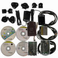
1321XDSK-BDM
Description
KIT STARTER DEV 1321X W/USB
Manufacturer
Freescale Semiconductor
Type
Sensor Demor
Specifications of 1321XDSK-BDM
Frequency
2.4GHz
Wireless Frequency
2.4 GHz
Interface Type
SPI
Modulation
DSSS OQPSK
Security
128 bit AES
Operating Voltage
2 VDC to 3.4 VDC
Output Power
2 dBm
Antenna
F-Antenna
Operating Temperature Range
- 40 C to + 85 C
For Use With/related Products
MC1321x
Lead Free Status / RoHS Status
Contains lead / RoHS compliant by exemption


3.2
3.3
Figure 5
Figure 5
(master) initiates all SPI transfers. During a transfer, the master shifts data out (on the MOSI pin) to the
slave while simultaneously shifting data in (on the MISO pin) from the slave. Although the SPI interface
supports simultaneous data exchange between master and slave, the modem SPI protocol only uses data
exchange in one direction at a time. The SPSCK signal is a clock output from the master and an input to
the slave. The slave device must be selected by a low level on the slave select input (SS1 pin).
Freescale Semiconductor
•
•
•
•
•
•
MCU bus master
Modem bus slave
Programmable SPI clock rate; maximum rate is 8 MHz
Double-buffered transmit and receive at MCU
Serial clock phase and polarity must meet modem requirements (MCU control bits
Slave select programmed to meet modem protocol
shows the SPI system level diagram.
shows the SPI modules of the MCU and modem in the master-slave arrangement. The MCU
SPI Features
SPI System Block Diagram
7
6
MCU (MASTER)
GENERATOR
SPI SHIFTER
5
CLOCK
4
3
2
1
0
MC13211/212/213 Technical Data, Rev. 1.8
Figure 5. SPI System Block Diagram
MOS1
MISO1
SPSCK1
PTE2/SS1
SPICLK
MOSI
MISO
CE
MODEM (SLAVE)
7
6
SPI SHIFTER
5
4
3
2
1
0
15
Related parts for 1321XDSK-BDM
Image
Part Number
Description
Manufacturer
Datasheet
Request
R

Part Number:
Description:
KIT STARTER DEVELOPER 1321X
Manufacturer:
Freescale Semiconductor
Datasheet:

Part Number:
Description:
Manufacturer:
Freescale Semiconductor, Inc
Datasheet:
Part Number:
Description:
Manufacturer:
Freescale Semiconductor, Inc
Datasheet:
Part Number:
Description:
Manufacturer:
Freescale Semiconductor, Inc
Datasheet:
Part Number:
Description:
Manufacturer:
Freescale Semiconductor, Inc
Datasheet:
Part Number:
Description:
Manufacturer:
Freescale Semiconductor, Inc
Datasheet:
Part Number:
Description:
Manufacturer:
Freescale Semiconductor, Inc
Datasheet:
Part Number:
Description:
Manufacturer:
Freescale Semiconductor, Inc
Datasheet:
Part Number:
Description:
Manufacturer:
Freescale Semiconductor, Inc
Datasheet:
Part Number:
Description:
Manufacturer:
Freescale Semiconductor, Inc
Datasheet:
Part Number:
Description:
Manufacturer:
Freescale Semiconductor, Inc
Datasheet:
Part Number:
Description:
Manufacturer:
Freescale Semiconductor, Inc
Datasheet:
Part Number:
Description:
Manufacturer:
Freescale Semiconductor, Inc
Datasheet:
Part Number:
Description:
Manufacturer:
Freescale Semiconductor, Inc
Datasheet:
Part Number:
Description:
Manufacturer:
Freescale Semiconductor, Inc
Datasheet: