1321XDSK-BDM Freescale Semiconductor, 1321XDSK-BDM Datasheet - Page 43
1321XDSK-BDM
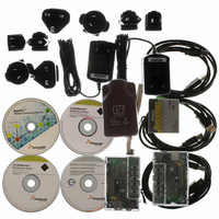
Manufacturer Part Number
1321XDSK-BDM
Description
KIT STARTER DEV 1321X W/USB
Manufacturer
Freescale Semiconductor
Type
Sensor Demor
Specifications of 1321XDSK-BDM
Frequency
2.4GHz
Wireless Frequency
2.4 GHz
Interface Type
SPI
Modulation
DSSS OQPSK
Security
128 bit AES
Operating Voltage
2 VDC to 3.4 VDC
Output Power
2 dBm
Antenna
F-Antenna
Operating Temperature Range
- 40 C to + 85 C
For Use With/related Products
MC1321x
Lead Free Status / RoHS Status
Contains lead / RoHS compliant by exemption


5.7.7
The HCS08 provides one 8-channel analog-to-digital (ATD) module. The eight ATD channels share
Port B. Each channel individually can be configured for general-purpose I/O or for ATD functionality.
5.7.7.1
5.7.7.2
The ATD has two modes for low power
5.7.7.2.1
When the MCU goes into Stop Mode, the MCU stops the clocks and the ATD analog circuitry is turned
off, placing the module into a low-power state. Once in stop mode, the ATD module aborts any single or
continuous conversion in progress. Upon exiting stop mode, no conversions occur and the registers have
their previous values. As long as the ATDPU bit is set prior to entering stop mode, the module is
reactivated coming out of stop.
5.7.7.2.2
Clearing the ATDPU bit in register ATD1C also places the ATD module in a low-power state. The ATD
conversion clock is disabled and the analog circuitry is turned off, placing the module in power-down
mode. (This mode does not remove power to the ATD module.) Once in power-down mode, the ATD
module aborts any conversion in progress. Upon setting the ATDPU bit, the module is reactivated. During
power-down mode, the ATD registers are still accessible.
Freescale Semiconductor
•
•
•
•
•
•
•
1. Stop mode
2. Power-down mode
8-/10-bit resolution
14.0 μsec, 10-bit single conversion time at a conversion frequency of 2 MHz
Left-/right-justified result data
Left-justified signed data mode
Conversion complete flag or conversion complete interrupt generation
Analog input multiplexer for up to eight analog input channels
Single or continuous conversion mode
Analog-to-Digital (ATD) Module
ATD Features
ATD Modes of Operation
ATD Stop Mode
ATD Power Down Mode
The reset state of the ATDPU bit is zero. Therefore, the module is reset into
the power-down state.
MC13211/212/213 Technical Data, Rev. 1.8
NOTE
43
Related parts for 1321XDSK-BDM
Image
Part Number
Description
Manufacturer
Datasheet
Request
R

Part Number:
Description:
KIT STARTER DEVELOPER 1321X
Manufacturer:
Freescale Semiconductor
Datasheet:

Part Number:
Description:
Manufacturer:
Freescale Semiconductor, Inc
Datasheet:
Part Number:
Description:
Manufacturer:
Freescale Semiconductor, Inc
Datasheet:
Part Number:
Description:
Manufacturer:
Freescale Semiconductor, Inc
Datasheet:
Part Number:
Description:
Manufacturer:
Freescale Semiconductor, Inc
Datasheet:
Part Number:
Description:
Manufacturer:
Freescale Semiconductor, Inc
Datasheet:
Part Number:
Description:
Manufacturer:
Freescale Semiconductor, Inc
Datasheet:
Part Number:
Description:
Manufacturer:
Freescale Semiconductor, Inc
Datasheet:
Part Number:
Description:
Manufacturer:
Freescale Semiconductor, Inc
Datasheet:
Part Number:
Description:
Manufacturer:
Freescale Semiconductor, Inc
Datasheet:
Part Number:
Description:
Manufacturer:
Freescale Semiconductor, Inc
Datasheet:
Part Number:
Description:
Manufacturer:
Freescale Semiconductor, Inc
Datasheet:
Part Number:
Description:
Manufacturer:
Freescale Semiconductor, Inc
Datasheet:
Part Number:
Description:
Manufacturer:
Freescale Semiconductor, Inc
Datasheet:
Part Number:
Description:
Manufacturer:
Freescale Semiconductor, Inc
Datasheet: