1321XDSK-BDM Freescale Semiconductor, 1321XDSK-BDM Datasheet - Page 41
1321XDSK-BDM
Manufacturer Part Number
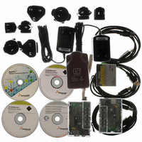
1321XDSK-BDM
Description
KIT STARTER DEV 1321X W/USB
Manufacturer
Freescale Semiconductor
Type
Sensor Demor
Specifications of 1321XDSK-BDM
Frequency
2.4GHz
Wireless Frequency
2.4 GHz
Interface Type
SPI
Modulation
DSSS OQPSK
Security
128 bit AES
Operating Voltage
2 VDC to 3.4 VDC
Output Power
2 dBm
Antenna
F-Antenna
Operating Temperature Range
- 40 C to + 85 C
For Use With/related Products
MC1321x
Lead Free Status / RoHS Status
Contains lead / RoHS compliant by exemption


5.7.6
The HCS08 microcontroller provides one inter-integrated circuit (IIC) module for communication with
other integrated circuits. The two pins associated with this module, SDA and SCL share port C pins 2 and
3, respectively. All functionality as described in this section is available on HCS08. When the IIC is
enabled, the direction of pins is controlled by module configuration. If the IIC is disabled, both pins can
be used as general-purpose I/O.
The inter-integrated circuit (IIC) provides a method of communication between a number of
devices{statement}. The interface is designed to operate up to 100 kbps with maximum bus loading and
timing. The device is capable of operating at higher baud rates, up to a maximum of clock/20, with reduced
bus loading. The maximum communication length and the number of devices that can be connected are
limited by a maximum bus capacitance of 400 pF.
5.7.6.1
The IIC includes these features:
5.7.6.2
The IIC functions the same in normal and monitor modes. A brief description of the IIC in the various
MCU modes is given here.
Run mode
Wait mode
Stop mode
Freescale Semiconductor
•
•
•
•
•
•
•
•
•
•
•
IP bus V2.0 compliant Compatible with IIC bus standard
Multi-master operation {statement}
Software programmable for one of 64 different serial clock frequencies {iic_prescale.asm}
Software selectable acknowledge bit {iic_ack.asm}
Interrupt driven byte-by-byte data transfer {iic_int.asm}
Arbitration lost interrupt with automatic mode switching from master to slave {iic_int.asm}
Calling address identification interrupt {iic_int.asm}
START and STOP signal generation/detection
{iic_transmit.asm}{iic_receive.asm}{iic_receive_addon.asm}
Repeated START signal generation {iic_transmit.asm}
Acknowledge bit generation/detection {iic_ack.asm}
Bus busy detection {iic_bus_busy.asm}
Inter-Integrated Circuit (IIC) Module
IIC Features
IIC Modes of Operation
This is the basic mode of operation. To conserve power in this mode, disable the
module.
The module will continue to operate while the MCU is in wait mode and can
provide a wake-up interrupt.
The IIC is inactive in Stop3 Mode for reduced power consumption. The STOP
instruction does not affect IIC register states. Stop1 and Stop2 will reset the
register contents.
MC13211/212/213 Technical Data, Rev. 1.8
41
Related parts for 1321XDSK-BDM
Image
Part Number
Description
Manufacturer
Datasheet
Request
R

Part Number:
Description:
KIT STARTER DEVELOPER 1321X
Manufacturer:
Freescale Semiconductor
Datasheet:

Part Number:
Description:
Manufacturer:
Freescale Semiconductor, Inc
Datasheet:
Part Number:
Description:
Manufacturer:
Freescale Semiconductor, Inc
Datasheet:
Part Number:
Description:
Manufacturer:
Freescale Semiconductor, Inc
Datasheet:
Part Number:
Description:
Manufacturer:
Freescale Semiconductor, Inc
Datasheet:
Part Number:
Description:
Manufacturer:
Freescale Semiconductor, Inc
Datasheet:
Part Number:
Description:
Manufacturer:
Freescale Semiconductor, Inc
Datasheet:
Part Number:
Description:
Manufacturer:
Freescale Semiconductor, Inc
Datasheet:
Part Number:
Description:
Manufacturer:
Freescale Semiconductor, Inc
Datasheet:
Part Number:
Description:
Manufacturer:
Freescale Semiconductor, Inc
Datasheet:
Part Number:
Description:
Manufacturer:
Freescale Semiconductor, Inc
Datasheet:
Part Number:
Description:
Manufacturer:
Freescale Semiconductor, Inc
Datasheet:
Part Number:
Description:
Manufacturer:
Freescale Semiconductor, Inc
Datasheet:
Part Number:
Description:
Manufacturer:
Freescale Semiconductor, Inc
Datasheet:
Part Number:
Description:
Manufacturer:
Freescale Semiconductor, Inc
Datasheet: