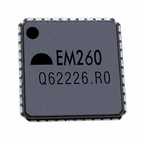
EM260-RTY Ember, EM260-RTY Datasheet - Page 23

EM260-RTY
Manufacturer Part Number
EM260-RTY
Description
IC ZIGBEE SYSTEM-ON-CHIP 40-QFN
Manufacturer
Ember
Specifications of EM260-RTY
Frequency
2.4GHz
Data Rate - Maximum
250kbps
Modulation Or Protocol
802.15.4
Applications
ZigBee™
Power - Output
-32dBm ~ 3dBm
Sensitivity
-97dBm
Voltage - Supply
2.1 V ~ 3.6 V
Current - Receiving
30mA
Current - Transmitting
34mA
Data Interface
PCB, Surface Mount
Antenna Connector
PCB, Surface Mount
Operating Temperature
-40°C ~ 85°C
Package / Case
40-QFN
Lead Free Status / RoHS Status
Lead free / RoHS Compliant
Memory Size
-
Other names
636-1003
5 SPI Protocol (Version Number 1)
5.1
5.2
Physical Interface Configuration
SPI Transaction
The EM260 Low Level Protocol centers on the SPI interface for communication with a pair of GPIO for hand-
shake signaling. The following are the primary design goals for the Low Level Protocol:
The EM260 supports both SPI Slave Mode 0 (clock is idle low, sample on rising edge) and SPI Slave Mode 3
(clock is idle high, sample on rising edge) at a maximum SPI clock rate of 5MHz, as illustrated in Figure 3. The
convention for the waveforms in this document is to show Mode 0.
The nHOST_INT signal and the nWAKE signal are both active low. The Host must supply a pull-up resistor on
the nHOST_INT signal to prevent errant interruptions during undefined events such as the EM260 resetting.
The EM260 supplies an internal pull-up on the nWAKE signal to prevent errant interruptions during undefined
events such as the Host resetting.
The basic EM260 SPI transaction is half-duplex to ensure proper framing and to give the EM260 adequate
response time. The basic transaction, as shown in Figure 4, is composed of three sections: Command, Wait,
and Response. The transaction can be considered analogous to a function call. The Command section is the
function call, and the Response section is the return value.
5.2.1
The Host begins the transaction by asserting the Slave Select and then sending a command to the EM260. This
command can be of any length from 2 to 128 bytes and must not begin with 0xFF. During the Command
section, the EM260 will respond with only 0xFF. The Host should ignore data on MISO during the Command
section. Once the Host has completed transmission of the entire message, the transaction moves to the Wait
section.
EM260 – Slave (MISO)
Host – Master (MOSI)
The EM260 looks like a hardware peripheral.
The EM260 is the slave device and all transactions are initiated by the Host (the master).
The EM260 supports a reasonably high data rate.
Command Section
Clock (SCLK)
Figure 4. General Timing Diagram for a SPI Transaction
Figure 3. SPI Transfer Format, Mode 0 and Mode 3
MSB
MSB
LSB
LSB
120-1003-000D
EM260
23


