E8MS-N0 Omron, E8MS-N0 Datasheet - Page 29
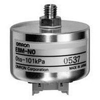
E8MS-N0
Manufacturer Part Number
E8MS-N0
Description
SENSOR PRESSURE NEGATIV 0-101KPA
Manufacturer
Omron
Series
E8MSr
Specifications of E8MS-N0
Pressure Type
Gauge
Operating Pressure
-14.65 ~ +0 PSI, -101 ~ 0 kPa
Port Size
Male, 1/8" (3.175mm) 27 NPT
Output
Digital
Voltage - Supply
12 V ~ 24 V
Termination Style
Cable
Operating Temperature
0°C ~ 50°C
Package / Case
Module
Sensor Output
Voltage
Supply Current
25mA
Voltage Rating
12V
Port Style
NPT, M5
Pressure Measurement Type
Gage
Operating Pressure Min
0psi
Terminal Type
Connector
Operating Pressure Max
14.6psi
Mounting Style
Desktop
Maximum Operating Temperature
+ 50 C
Minimum Operating Temperature
0 C
Operating Supply Voltage
12 V
Output Voltage
1 V to 5 V
Pressure Port
Y
Sensor Type
Sensors
Lead Free Status / RoHS Status
Lead free / RoHS Compliant
Lead Free Status / RoHS Status
Lead free / RoHS Compliant, Lead free / RoHS Compliant
Other names
E8MSN0


Precautions
J APPLICATIONS
You must allow sufficient leeway in ratings and performance and
provide proper fail-safe and other safety measures when using the
Link the E8M in any of the following applications. Be sure also to
consult with your OMRON representative before actually attempt-
ing any of these applications.
1. Applications under conditions or environments not specified
2. Applications for nuclear reactor control, train facilities, avi-
3. Applications strongly related to human life or property, partic-
J WARNINGS
Environment
Do not use the Sensor in locations subject to explosive or
flammable gases.
Power Supply Voltage
Do not apply voltages in excess of the specified power supply
voltage range. Applying voltages beyond the specified range may
result in burning.
Short-circuit in Load
Do not short-circuit the load. Short-circuit the load may result in
breaking or burning.
Incorrect Wiring
Be sure to connect to the polarities of the power supply correctly
and avoid incorrect wiring. Incorrect connection or wiring may
result in breaking or burning.
E8M/E8MS
in the instructions sheets.
ation facilities, motorized vehicles, furnaces, medical equip-
ment, amusement equipment, and safety equipment.
ularly those requiring safety.
30
J CORRECT USE
Connecting and Locking the E8MS Sensor I/O Con-
nector (E89-M4)
1. Hold both ends of the female connector connected to the
2. A lock cover is slid through the Sensor I/O Connector to pre-
3. To unlock the connector, rotate the lock cover counterclock-
Note: Forcibly pulling the cable to disconnect the connector may
Sensor I/O Connector so that the protrusion on the female
connector faces upward, orientate the hole in the male con-
nector on the Sensor upwards, and insert the female connec-
tor into the hole until the protrusion clicks in.
vent it from coming free due to vibration or shock.
Insert the lock cover facing in the correct direction (a) as
shown in the following figure, and rotate it clockwise (b) until
it clicks in.
wise until it clicks, then pull it towards you.
To disconnect the connector, hold both ends of the connector,
then pull it towards you.
damage the pressure-welded portion. Be sure to hold both
ends of the connector when disconnecting it.
Lock cover
Lock
Lock cover
(a)
(b)
Unlock
E8M/E8MS
Related parts for E8MS-N0
Image
Part Number
Description
Manufacturer
Datasheet
Request
R

Part Number:
Description:
SENSOR PRESSURE POSITIV 0-100KPA
Manufacturer:
Omron
Datasheet:

Part Number:
Description:
SENSOR PRESSURE POSITIVE 0-1MPA
Manufacturer:
Omron
Datasheet:

Part Number:
Description:
G6S-2GLow Signal Relay
Manufacturer:
Omron Corporation
Datasheet:
Part Number:
Description:
Compact, Low-cost, SSR Switching 5 to 20 A
Manufacturer:
Omron Corporation
Datasheet:
Part Number:
Description:
Manufacturer:
Omron Corporation
Datasheet:
Part Number:
Description:
Manufacturer:
Omron Corporation
Datasheet:
Part Number:
Description:
Manufacturer:
Omron Corporation
Datasheet:
Part Number:
Description:
Manufacturer:
Omron Corporation
Datasheet:
Part Number:
Description:
Manufacturer:
Omron Corporation
Datasheet: