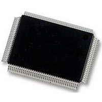
DP83865DVH National Semiconductor, DP83865DVH Datasheet - Page 21

DP83865DVH
Manufacturer Part Number
DP83865DVH
Description
10/100/1000BASE-T TRANSCEIVER, SMD
Manufacturer
National Semiconductor
Specifications of DP83865DVH
Data Rate
1000Mbps
No. Of Ports
1
Ethernet Type
IEEE 802.3u, IEEE 802.3z
Supply Current
430µA
Supply Voltage Range
2.375V To 2.625V, 3.135V To 3.465V
Operating Temperature Range
0°C To +70°C
Interface Type
GMII, MII, RGMII
Rohs Compliant
Yes
Leaded Process Compatible
No
Peak Reflow Compatible (260 C)
No
Lead Free Status / RoHS Status
Lead free / RoHS Compliant
Available stocks
Company
Part Number
Manufacturer
Quantity
Price
Company:
Part Number:
DP83865DVH
Manufacturer:
Texas Instruments
Quantity:
10 000
Company:
Part Number:
DP83865DVH/NOPB
Manufacturer:
NXP
Quantity:
1 000
Company:
Part Number:
DP83865DVH/NOPB
Manufacturer:
Texas Instruments
Quantity:
10 000
2.0 Register Block
2.3 Register Description
In the register description under the ‘Default’ heading, the following definitions hold true:
— RW
— RO
— LH
— LL
— SC
— P
— STRAP[x] = Default value read from Strapped value at device pin at Reset, where x may take the values:
Bit
15
14
13
12
= Read Write access
= Read Only access
= Latched High until read, based upon the occurrence of the corresponding event
= Latched Low until read, based upon the occurrence of the corresponding event
= Register sets on event occurrence (or is manually set) and Self-Clears when event ends
= Register bit is Permanently set to a default value
[0] internal pull-down
[1] internal pull-up
Bit Name
Loopback
Speed[0]
AN_EN
Reset
(Continued)
Table 3. Basic Mode Control Register (BMCR) address 0x00
STRAP[0], RW Speed Select:
STRAP[1], RW Auto-Negotiation Enable:
0, RW, SC
Default
0, RW
Reset:
1 = Initiate software Reset / Reset in Process.
0 = Normal operation.
This bit sets the status and control registers of the PHY to their
default states. This bit, which is self-clearing, returns a value of
one until the reset process is complete (approximately 1.2 ms for
reset duration). Reset is finished once the Auto-Negotiation pro-
cess has begun or the device has entered it’s forced mode.
Loopback:
1 = Loopback enabled.
0 = Normal operation.
The loopback function enables MII/GMII transmit data to be rout-
ed to the MII/GMII receive data path. The data loops around at
the DAC/ADC Subsystem (see block diagram page 2), bypassing
the Drivers/Receivers block. This exercises most of the PHY’s in-
ternal logic.
When Auto-Negotiation is disabled, bits 6 and 13 select device
speed selection per table below:
(The default value of this bit is = to the strap value of pin 7 during
reset/power-on IF Auto-Negotiation is disabled.)
1 = Auto-Negotiation Enabled - bits 6, 8 and 13 of this register are
ignored when this bit is set.
0 = Auto-Negotiation Disabled - bits 6, 8 and 13 determine the link
speed and mode.
(The default value of this bit is = to the strap value of pin 10 during
reset/power-on.)
Speed[1]
21
1
1
0
0
Speed[0]
1
0
1
0
Description
Speed Enabled
= Reserved
= 1000 Mbps
= 100 Mbps
= 10 Mbps
www.national.com


