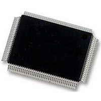
DP83865DVH National Semiconductor, DP83865DVH Datasheet - Page 62

DP83865DVH
Manufacturer Part Number
DP83865DVH
Description
10/100/1000BASE-T TRANSCEIVER, SMD
Manufacturer
National Semiconductor
Specifications of DP83865DVH
Data Rate
1000Mbps
No. Of Ports
1
Ethernet Type
IEEE 802.3u, IEEE 802.3z
Supply Current
430µA
Supply Voltage Range
2.375V To 2.625V, 3.135V To 3.465V
Operating Temperature Range
0°C To +70°C
Interface Type
GMII, MII, RGMII
Rohs Compliant
Yes
Leaded Process Compatible
No
Peak Reflow Compatible (260 C)
No
Lead Free Status / RoHS Status
Lead free / RoHS Compliant
Available stocks
Company
Part Number
Manufacturer
Quantity
Price
Company:
Part Number:
DP83865DVH
Manufacturer:
Texas Instruments
Quantity:
10 000
Company:
Part Number:
DP83865DVH/NOPB
Manufacturer:
NXP
Quantity:
1 000
Company:
Part Number:
DP83865DVH/NOPB
Manufacturer:
Texas Instruments
Quantity:
10 000
www.national.com
4.0 Functional Description
4.9.4 PHY Address Sensing
The DP83865 provides five PHY address pins to set the
PHY address. The information is latched into the
STRAP_REG 0x10.4:0 at device power-up or reset. The
DP83865
1(<00001>) through 31(<11111>). Note that PHY address 0
by default is the broadcast write address and should not be
used as the PHY address.
4.9.5 MII Data Interface
Clause 22 of the IEEE 802.3u specification defines the
Media Independent Interface. This interface includes a
dedicated receive bus and a dedicated transmit bus. These
two data buses, along with various control and indicate sig-
nals, allow for the simultaneous exchange of data between
the DP83865 and the upper layer agent (MAC).
The receive interface consists of a nibble wide data bus
RXD[3:0], a receive error signal RX_ER, a receive data
valid flag RX_DV, and a receive clock RX_CLK for syn-
chronous transfer of the data. The receive clock operates
at 25 MHz to support 100 Mb/s and 2.5 MHz for 10 Mb/s
operation.
The transmit interface consists of a nibble wide data bus
TXD[3:0], a transmit error flag TX_ER, a transmit enable
control signal TX_EN, and a transmit clock TX_CLK oper-
ates at 25 MHz for 100 Mb/s and 2.5 MHz for 10 Mb/s.
Additionally, the MII includes the carrier sense signal CRS,
as well as a collision detect signal COL. The CRS signal
asserts to indicate the reception of data from the network
or as a function of transmit data in Half Duplex mode. The
COL signal asserts as an indication of a collision which can
occur during Half Duplex operation when both a transmit
and receive operation occur simultaneously.
4.9.6 MII Isolate Mode
The DP83865 can be forced to electrically isolate its data
paths from the MII or GMII by setting the BMCR 0x00.10 to
“1”. Clearing BMCR 0x00.10 returns PHY back to normal
operation.
In Isolate Mode, the DP83865 does not respond to packet
data present at TXD, TX_EN, and TX_ER inputs and pre-
sents a high impedance on the TX_CLK, RX_CLK, RX_DV,
RX_ER, RXD, COL, and CRS outputs. The DP83865 will
continue to respond to all serial management transactions
over the MDIO/MDC lines.
The IEEE 802.3u neither requires nor assumes any spe-
cific behavior at the MDI while in Isolate mode. For
DP83685, all MDI operations are halted.
MDC
MDIO
(STA)
supports
Z
Idle
Z
0
Start
1
PHY
Opcode
(Write)
0
1
0
Address
(PHYAD = 0Ch)
PHY Address
1 1 0 0 0 0 0 0 0
Figure 12. Typical MDC/MDIO Write Operation
(Continued)
strapping
Register Address
(00h = BMCR)
values
1
62
TA
0 0 0
4.9.7 Status Information
There are five LED driver pins associated with each port
indicating status information. Status information include
combined link and speed, duplex, and activity.
LINK10_LED: 10 BASE-T link is established by detecting
Normal Link Pulses separated by 16 ms or by packet data
received.
LINK100_LED: 100BASE-TX link is established when the
PHY receives an signal with amplitude compliant with TP-
PMD specifications. This results in an internal generation
of Signal Detect.
LINK1000_LED: 1000BASE-T link is established when
Auto-Negotiation has been completed and reliable recep-
tion of signals has been received from a remote PHY.
Link asserts after the internal Signal Detect remains
asserted for a minimum of 500 ms. Link will de-assert
immediately following the de-assertion of the internal Sig-
nal Detect.
ACTIVITY_LED: Activity status indicates the PHY is receiv-
ing data, transmitting data or detecting idle error.
DUPLEX_LED: Duplex indicates that the Gig PHYTER is in
Full-Duplex mode of operation when LED is lit.
0 0
0 0 0
Register Data
0
0 0 0 0 0 0 0 0
Z
Idle
Z


