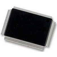
DP83865DVH National Semiconductor, DP83865DVH Datasheet - Page 48

DP83865DVH
Manufacturer Part Number
DP83865DVH
Description
10/100/1000BASE-T TRANSCEIVER, SMD
Manufacturer
National Semiconductor
Specifications of DP83865DVH
Data Rate
1000Mbps
No. Of Ports
1
Ethernet Type
IEEE 802.3u, IEEE 802.3z
Supply Current
430µA
Supply Voltage Range
2.375V To 2.625V, 3.135V To 3.465V
Operating Temperature Range
0°C To +70°C
Interface Type
GMII, MII, RGMII
Rohs Compliant
Yes
Leaded Process Compatible
No
Peak Reflow Compatible (260 C)
No
Lead Free Status / RoHS Status
Lead free / RoHS Compliant
Available stocks
Company
Part Number
Manufacturer
Quantity
Price
Company:
Part Number:
DP83865DVH
Manufacturer:
Texas Instruments
Quantity:
10 000
Company:
Part Number:
DP83865DVH/NOPB
Manufacturer:
NXP
Quantity:
1 000
Company:
Part Number:
DP83865DVH/NOPB
Manufacturer:
Texas Instruments
Quantity:
10 000
www.national.com
3.0 Configuration
During transmit BIST operation the transmit path
(TXD[7:0]) of the GMII / MII is disabled. All generated pack-
ets will be sent out to the MDI path unless the loopback
mode is enabled. In that case the generated packets will be
presented at the receive path (RXD[7:0]) of the GMII / MII.
If BIST is operating the 1000BASE-T mode, active
GTX_CLK is required for the operation.
3.19 Cable Length Indicator
The maximum CAT5 cable length specified in IEEE 802.3
is 100 meters. When cable length extended beyond the
IEEE specified range, bit error rate (BER) will increase due
to the degredation of signal-to-noise ratio. The DP83865
has enough margin built-in to work at extended cable
reach.
When a 100BASE-TX or 1000BASE-T link is established,
the cable length is determined from adaptation parameters.
In 100BASE-TX mode, one cable length measurement is
available since there is one receive channel. In 1000BASE-
T mode, four cable length measurements are available
since there are four receive channels. Each measurement
is stored in an 8-bit register in the expanded memory
space. User may choose to take the average of four mea-
surement to achieve more accurate result. The number
stored in the cable length registers are in meters, and the
typical accuracy is 5 meters.
The error rate may be used in conjuction with the cable
length measurement to determine if the link is within IEEE
specifications. If the measurement shows that the cable
length exceeds 130 meters, either the cable is too long or
the cable quality is not meeting the CAT5 standard.
Length_C
Length_D
Length_A
Length_B
Regiters
13:11
Table 49. Cable Length Indicator Registers
Bit
Table 48. BIST Configuration 2 Reg (0x1A)
15
14
Function
‘1’ = Enable counter
Counter selection:
‘1’ = upper 16-bit
‘0’ = lower 16-bit
Number of packets to transmit:
‘000’ = continuous transmit
‘001’ = 1 packet
‘010’ = 10 packets
‘011’ = 100 packets
‘100’ = 1,000 packets
‘101’ = 10,000 packets
‘110’ = 100,000 packets
‘111’ = 10,000,000 packets
0x01A2
0x01A5
0x01A8
0x019F
Addr
(Continued)
Length, 100/1000 Mbps
Length, 1000 Mbps
Length, 1000 Mbps
Length, 1000 Mbps
Description
48
3.20 10BASE-T Half Duplex Loopback
By default, the 10BASE-T half duplex transmitted packets
are looped back to the receive side. This is a legacy imple-
mentation. However, in the latest MAC or switch design,
the 10 Mbps loopback is desired to be turned off. The 10
Mbps HDX loopback can be disabled in the expanded
memory register 0x1C0.1.
3.21 I/O Voltage Selection
There are two options for the I/O voltage available. All
IO_VDD pins must be connected to the same power sup-
ply. It can either be 2.5V or 3.3V. The VDD_SEL pin must
be connected to ground in order to select 2.5V or to the
3.3V power supply to select 3.3 V. This pin must be con-
nected directly to the respective power supply and must
not use a pull-up/-down resistor.
Pin which are effected by IO_VDD, i.e. will be driven at a
different voltage level, are all pin on the GMII/MII interface,
management interface, JTAG interface, clock interface,
device configuration and reset pins.
3.22 Non-compliant inter-operability mode
In this mode the DP83865 allows with other vendor’s first
generation 1000 Mbps PHYs. National’s DP83865 is com-
pliant to IEEE 802.3ab and optionally inter-operable with
non-compliant PHYs.
To enter non-compliant inter-operability mode the user can
use a 2k
‘1’ to bit 9 of register 0x12.
The non-compliant mode is functional in auto-negotiation
configuration. It is not applicable in manual speed configu-
ration.
Table 50. 10M FDX Loopback Disable, Reg 0x1C0
Bit 1
0
1
resistor on NON_IEEE_STRAP (pin 1) or write
10BASE-T HDX loopback enabled
10BASE-T HDX loopback disabled
10BASE-T HDX Loopback Mode


