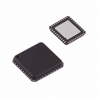
ADUC7020BCPZ62I-RL Analog Devices Inc, ADUC7020BCPZ62I-RL Datasheet - Page 11

ADUC7020BCPZ62I-RL
Manufacturer Part Number
ADUC7020BCPZ62I-RL
Description
IC,MICROCONTROLLER,16-BIT,ARM7 CPU,CMOS,LLCC,40PIN,PLASTIC
Manufacturer
Analog Devices Inc
Series
MicroConverter® ADuC7xxxr
Datasheet
1.USB-I2CLIN-CONV-Z.pdf
(96 pages)
Specifications of ADUC7020BCPZ62I-RL
Core Processor
ARM7
Core Size
16/32-Bit
Speed
44MHz
Connectivity
EBI/EMI, I²C, SPI, UART/USART
Peripherals
PLA, PWM, PSM, Temp Sensor, WDT
Number Of I /o
14
Program Memory Size
62KB (62K x 8)
Program Memory Type
FLASH
Ram Size
8K x 8
Voltage - Supply (vcc/vdd)
2.7 V ~ 3.6 V
Data Converters
A/D 5x12b; D/A 4x12b
Oscillator Type
Internal
Operating Temperature
-40°C ~ 125°C
Package / Case
40-LFCSP
Lead Free Status / RoHS Status
Lead free / RoHS Compliant
For Use With
EVAL-ADUC7020QSZ - KIT DEV ADUC7020 QUICK STARTEVAL-ADUC7020MKZ - KIT MINI DEV FOR ADUC7026/7027
Eeprom Size
-
Lead Free Status / RoHS Status
Lead free / RoHS Compliant
Available stocks
Company
Part Number
Manufacturer
Quantity
Price
Part Number:
ADUC7020BCPZ62I-RL
Manufacturer:
ADI/亚德诺
Quantity:
20 000
Table 4 I
Parameter
t
t
t
t
t
t
t
t
t
t
t
1
Table 5. I
Parameter
t
t
t
t
t
t
t
t
t
t
1
L
H
SHD
DSU
DHD
RSU
PSU
BUF
R
F
SUP
L
H
SHD
DSU
DHD
RSU
PSU
BUF
R
F
t
t
HCLK
HCLK
depends on the clock divider or CD bits in the PLLCON MMR. t
depends on the clock divider or CD bits in the PLLCON MMR. t
SDATA (I/O)
2
2
C Timing in Fast Mode (400 kHz)
SCLK (I)
C Timing in Standard Mode (100 kHz)
t
PSU
Description
SCLOCK low pulse width
SCLOCK high pulse width
Start condition hold time
Data setup time
Data hold time
Setup time for repeated start
Stop condition setup time
Bus-free time between a stop condition and a start condition
Rise time for both CLOCK and SDATA
Fall time for both CLOCK and SDATA
Pulse width of spike suppressed
Description
SCLOCK low pulse width
SCLOCK high pulse width
Start condition hold time
Data setup time
Data hold time
Setup time for repeated start
Stop condition setup time
Bus-free time between a stop condition and a start condition
Rise time for both CLOCK and SDATA
Fall time for both CLOCK and SDATA
CONDITION
STOP
P
t
BUF
CONDITION
START
S
t
DSU
t
SHD
1
1
1
1
MSB
1
Figure 5. I
t
DHD
HCLK
HCLK
2–7
= t
= t
2
Rev. C | Page 11 of 96
C Compatible Interface Timing
UCLK
UCLK
/2
/2
t
t
CD
CD
H
L
; see Figure 57.
; see Figure 57.
LSB
8
t
SUP
ADuC7019/20/21/22/24/25/26/27/28/29
t
DSU
t
SUP
ACK
9
t
RSU
t
DHD
Min
200
100
300
100
0
100
100
1.3
Min
4.7
4.0
4.0
250
0
4.7
4.0
4.7
REPEATED
START
S(R)
Slave
Slave
Max
300
300
50
Max
3.45
1
300
t
F
Master
Typ
1360
1140
251,350
740
400
12.51350
400
200
MSB
t
F
1
Master
Typ
t
R
t
R
Unit
μs
ns
μs
ns
μs
μs
μs
μs
μs
ns
Unit
ns
ns
ns
ns
ns
ns
ns
μs
ns
ns
ns


