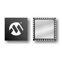
PIC16F1937-E/MV Microchip Technology, PIC16F1937-E/MV Datasheet - Page 67

PIC16F1937-E/MV
Manufacturer Part Number
PIC16F1937-E/MV
Description
14KB Flash, 512B RAM, 256B EEPROM, LCD, 1.8-5.5V 40 UQFN 5x5x0.5mm TUBE
Manufacturer
Microchip Technology
Series
PIC® XLP™ 16Fr
Datasheet
1.PIC16F1937-EMV.pdf
(472 pages)
Specifications of PIC16F1937-E/MV
Processor Series
PIC16F
Core
PIC
Program Memory Type
Flash
Program Memory Size
14 KB
Data Ram Size
256 B
Interface Type
MI2C, SPI, EUSART
Number Of Timers
5
Operating Supply Voltage
1.8 V to 5.5 V
Maximum Operating Temperature
+ 125 C
Mounting Style
SMD/SMT
Package / Case
UQFN-40
Development Tools By Supplier
MPLAB IDE Software
Minimum Operating Temperature
- 40 C
Core Processor
PIC
Core Size
8-Bit
Speed
32MHz
Connectivity
I²C, LIN, SPI, UART/USART
Peripherals
Brown-out Detect/Reset, LCD, POR, PWM, WDT
Number Of I /o
36
Eeprom Size
256 x 8
Ram Size
512 x 8
Voltage - Supply (vcc/vdd)
1.8 V ~ 5.5 V
Data Converters
A/D 14x10b
Oscillator Type
Internal
Operating Temperature
-40°C ~ 125°C
Lead Free Status / Rohs Status
Details
- Current page: 67 of 472
- Download datasheet (5Mb)
5.0
5.1
The oscillator module has a wide variety of clock
sources and selection features that allow it to be used
in a wide range of applications while maximizing perfor-
mance and minimizing power consumption.
illustrates a block diagram of the oscillator module.
Clock sources can be supplied from external oscillators,
quartz crystal resonators, ceramic resonators and
Resistor-Capacitor (RC) circuits. In addition, the system
clock source can be supplied from one of two internal
oscillators and PLL circuits, with a choice of speeds
selectable via software. Additional clock features
include:
• Selectable system clock source between external
• Two-Speed Start-up mode, which minimizes
• Fail-Safe Clock Monitor (FSCM) designed to
• Oscillator Start-up Timer (OST) ensures stability
2008-2011 Microchip Technology Inc.
or internal sources via software.
latency between external oscillator start-up and
code execution.
detect a failure of the external clock source (LP,
XT, HS, EC or RC modes) and switch
automatically to the internal oscillator.
of crystal oscillator sources
OSCILLATOR MODULE (WITH
FAIL-SAFE CLOCK MONITOR)
Overview
Figure 5-1
The oscillator module can be configured in one of eight
clock modes.
1.
2.
3.
4.
5.
6.
7.
8.
Clock Source modes are selected by the FOSC<2:0>
bits in the Configuration Word 1. The FOSC bits
determine the type of oscillator that will be used when
the device is first powered.
The EC clock mode relies on an external logic level
signal as the device clock source. The LP, XT, and HS
clock modes require an external crystal or resonator to
be connected to the device. Each mode is optimized for
a different frequency range. The RC clock mode
requires an external resistor and capacitor to set the
oscillator frequency.
The INTOSC internal oscillator block produces low,
medium, and high frequency clock sources, designated
LFINTOSC,
Internal Oscillator Block,
of device clock frequencies may be derived from these
three clock sources.
ECL – External Clock Low-Power mode
(0 MHz to 0.5 MHz)
ECM – External Clock Medium-Power mode
(0.5 MHz to 4 MHz)
ECH – External Clock High-Power mode
(4 MHz to 32 MHz)
LP – 32 kHz Low-Power Crystal mode.
XT – Medium Gain Crystal or Ceramic Resonator
Oscillator mode (up to 4 MHz)
HS – High Gain Crystal or Ceramic Resonator
mode (4 MHz to 20 MHz)
RC – External Resistor-Capacitor (RC).
INTOSC – Internal oscillator (31 kHz to 32 MHz).
PIC16(L)F1934/6/7
MFINTOSC,
Figure
and
5-1). A wide selection
HFINTOSC.
DS41364E-page 67
(see
Related parts for PIC16F1937-E/MV
Image
Part Number
Description
Manufacturer
Datasheet
Request
R

Part Number:
Description:
IC, 8BIT MCU, PIC16F, 32MHZ, SOIC-18
Manufacturer:
Microchip Technology
Datasheet:

Part Number:
Description:
IC, 8BIT MCU, PIC16F, 32MHZ, SSOP-20
Manufacturer:
Microchip Technology
Datasheet:

Part Number:
Description:
IC, 8BIT MCU, PIC16F, 32MHZ, DIP-18
Manufacturer:
Microchip Technology
Datasheet:

Part Number:
Description:
IC, 8BIT MCU, PIC16F, 32MHZ, QFN-28
Manufacturer:
Microchip Technology
Datasheet:

Part Number:
Description:
IC, 8BIT MCU, PIC16F, 32MHZ, QFN-28
Manufacturer:
Microchip Technology
Datasheet:

Part Number:
Description:
IC, 8BIT MCU, PIC16F, 32MHZ, QFN-28
Manufacturer:
Microchip Technology
Datasheet:

Part Number:
Description:
IC, 8BIT MCU, PIC16F, 32MHZ, SSOP-20
Manufacturer:
Microchip Technology
Datasheet:

Part Number:
Description:
IC, 8BIT MCU, PIC16F, 20MHZ, DIP-40
Manufacturer:
Microchip Technology
Datasheet:

Part Number:
Description:
IC, 8BIT MCU, PIC16F, 32MHZ, QFN-28
Manufacturer:
Microchip Technology
Datasheet:

Part Number:
Description:
IC, 8BIT MCU, PIC16F, 20MHZ, MQFP-44
Manufacturer:
Microchip Technology
Datasheet:

Part Number:
Description:
IC, 8BIT MCU, PIC16F, 20MHZ, QFN-20
Manufacturer:
Microchip Technology
Datasheet:

Part Number:
Description:
IC, 8BIT MCU, PIC16F, 32MHZ, QFN-28
Manufacturer:
Microchip Technology
Datasheet:

Part Number:
Description:
MCU 14KB FLASH 768B RAM 64-TQFP
Manufacturer:
Microchip Technology
Datasheet:

Part Number:
Description:
7 KB Flash, 384 Bytes RAM, 32 MHz Int. Osc, 16 I/0, Enhanced Mid Range Core, Low
Manufacturer:
Microchip Technology

Part Number:
Description:
14KB Flash, 512B RAM, 256B EEPROM, LCD, 1.8-5.5V 40 UQFN 5x5x0.5mm TUBE
Manufacturer:
Microchip Technology


