20-101-0356 Rabbit Semiconductor, 20-101-0356 Datasheet - Page 25
20-101-0356
Manufacturer Part Number
20-101-0356
Description
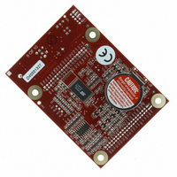
COMPUTER SINGLE-BOARD BL1800
Manufacturer
Rabbit Semiconductor
Datasheet
1.20-101-0356.pdf
(94 pages)
Specifications of 20-101-0356
Module/board Type
Single Board Computer Module
Product
Modules
Data Bus Width
8 bit
Processor Type
Rabbit 2000
Sram
128 KB
Flash
256 KB
Timers
8 bit, 10 bit
Number Of I/os
14
Backup Battery
3 V Lithium Coin Type
Operating Voltage
8 V to 40 V
Power Consumption
1.2 W
Board Size
89 mm x 64 mm x 19 mm
Description/function
Computer Module
For Use With/related Products
BL1800
Lead Free Status / RoHS Status
Lead free / RoHS Compliant
Other names
316-1079


3.3 A/D Converter
The analog-to-digital (A/D) converter, shown in Figure 9, compares the DA0 voltage to
AD0, the voltage presented to the converter. DA0 therefore cannot be used for the digital-
to-analog (D/A) converter when the A/D converter is being used.
The A/D converter transforms the voltage at DA0 into a 20 mV window centered around
DA0. For example, if DA0 is 2.0 V, the window in the A/D converter would be 1.990 V to
2.010 V. If AD0 > 2.010 V, PE7 would read high and PE6 would read low. If 1.990 V <
AD0 < 2.010 V, PE7 would read low and PE6 would read low. This is the case when the
A/D input is exactly the same as DA0. If AD0 < 1.990 V, PE7 would read low and PE6
would read high.
PE6 can be imagined to be a “DA0 voltage is too high” indicator. If DA0 is larger than the
analog voltage presented at AD0, then PE6 will be true (high). If this happens, the pro-
gram will need to reduce the DA0 voltage.
PE7 can be imagined to be a “DA0 voltage is too low” indicator. If DA0 is smaller than
the analog voltage presented at AD0, then PE7 will be true (high). If this happens, the pro-
gram will need to raise the DA0 voltage.
The A/D input, AD0, is the same as DA0 only when PE6 and PE7 are low. Because the
A/D converter circuit uses a 20 mV window, the accuracy is ±10 mV. DA0 can range from
0.1 V to 2.8 V, which represents 270 steps of ±10 mV. This is better than 8-bit accuracy.
Since the D/A converter is able to change the DA0 output in 3.88 mV steps, there are 697
steps over the range from 0.1 V to 2.8 V. This represents a resolution of more than 9 bits.
User’s Manual
Figure 9. Schematic Diagram of A/D Converter
W
W
W
W
W
W
W
21
Related parts for 20-101-0356
Image
Part Number
Description
Manufacturer
Datasheet
Request
R

Part Number:
Description:
COMPUTER SGL-BRD BL2500 29.4MHZ
Manufacturer:
Rabbit Semiconductor
Datasheet:

Part Number:
Description:
COMPUTER SGL-BRD BL2500 29.4MHZ
Manufacturer:
Rabbit Semiconductor
Datasheet:

Part Number:
Description:
DISPLAY GRAPHIC 12KEY PROG OP670
Manufacturer:
Rabbit Semiconductor
Datasheet:
Part Number:
Description:
DISPLAY GRAPHIC 12KEY ETH OP6700
Manufacturer:
Rabbit Semiconductor
Datasheet:

Part Number:
Description:
COMPUTER SINGLE-BOARD BL2030
Manufacturer:
Rabbit Semiconductor
Part Number:
Description:
COMPUTER SGL-BOARD ETH BL2010
Manufacturer:
Rabbit Semiconductor

Part Number:
Description:
MODULE OP6810 W/O ETH/MEM EXPANS
Manufacturer:
Rabbit Semiconductor
Datasheet:
Part Number:
Description:
COMPUTER SINGLE-BOARD BL2020
Manufacturer:
Rabbit Semiconductor
Part Number:
Description:
COMPUTER BL2010 W/FRICTION LOCK
Manufacturer:
Rabbit Semiconductor
Part Number:
Description:
COMPUTER BL2020 W/FRICTION LOCK
Manufacturer:
Rabbit Semiconductor
Part Number:
Description:
COMPUTER SGL-BRD BL2500 44.2MHZ
Manufacturer:
Rabbit Semiconductor
Datasheet:
Part Number:
Description:
COMPUTER SGL-BOARD FULL BL2000
Manufacturer:
Rabbit Semiconductor

Part Number:
Description:
COMPUTER SINGLE-BOARD BL2110
Manufacturer:
Rabbit Semiconductor

Part Number:
Description:
COMPUTER SGL-BRD 29.4MHZ BL2610
Manufacturer:
Rabbit Semiconductor
Datasheet:
Part Number:
Description:
INTERFACE OP6800 512K FLASH&SRAM
Manufacturer:
Rabbit Semiconductor
Datasheet: