20-101-0356 Rabbit Semiconductor, 20-101-0356 Datasheet - Page 48
20-101-0356
Manufacturer Part Number
20-101-0356
Description
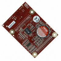
COMPUTER SINGLE-BOARD BL1800
Manufacturer
Rabbit Semiconductor
Datasheet
1.20-101-0356.pdf
(94 pages)
Specifications of 20-101-0356
Module/board Type
Single Board Computer Module
Product
Modules
Data Bus Width
8 bit
Processor Type
Rabbit 2000
Sram
128 KB
Flash
256 KB
Timers
8 bit, 10 bit
Number Of I/os
14
Backup Battery
3 V Lithium Coin Type
Operating Voltage
8 V to 40 V
Power Consumption
1.2 W
Board Size
89 mm x 64 mm x 19 mm
Description/function
Computer Module
For Use With/related Products
BL1800
Lead Free Status / RoHS Status
Lead free / RoHS Compliant
Other names
316-1079


4.2.2 Other Sample Programs Illustrating Digital I/O
•
•
•
•
Before running the
install 3 mm LEDs such as the Vishay Telefunken TLUR4400 at DS5–DS8 on the Jack-
rabbit Prototyping Board. These LEDs are included with the Jackrabbit Development Kit.
•
•
44
DEMOJR2.C
typing Board.
This sample program also illustrates the use of the
Dynamic C to update watch expressions while running. To test this:
DEMOJR3.C
by PA3) on the Prototyping Board. This sample program will also watch button S1
(PB2) and toggle LED DS1 (which is controlled by PA0) on/off when pressed. Note
that S1 presses are debounced by the software.
The pins on Parallel Port A can all be set as either outputs or as inputs via the slave port
control register (SPCTR). Do not use Parallel Port A if the slave port is being used.
Bits 0–5 on Parallel Port B are always inputs, and bits 6–7 are always outputs. Do not
use Parallel Port B if the slave port is being used.
JRIOTEST.C
input channel, and the two analog output channels.
JRIO_COF.C
Before you run this sample program, connect DA1 to AD0 on header J7 of the Proto-
typing Board to provide an input voltage. Once the sample program is running, it will
read the input voltage ten times while another costatement is executed concurrently. The
values will be printed out in the Dynamic C
RABDB01.C
connected to PA4–PA7) when corresponding switches S1–S4 (which are connected to
PB2–PB5) are pressed. The buzzer, which is driven by HV0 from PE0, will also sound
whenever switch S1 switch is pressed.
RABDB02.C
connected to PA4–PA7) when corresponding switches S1–S4 (which are connected to
PB2–PB5) are pressed. The buzzer, which is driven by HV0 from PE0, will also sound
whenever switch S1 switch is pressed.
1. Add a watch expression for "k" under "Inspect:Add/Del Watch Expression."
2. Click "Add to top" so that it will be permanently in the watch list.
3. While the program is running, type
—repeatedly flashes LED DS3 (which is controlled by PA2) on the Proto-
—demonstrates the use of costatements to LED DS4 (which is controlled
—flashes LEDs DS5–DS8 on the Jackrabbit Prototyping Board (which are
—flashes LEDs DS5–DS8 on the Jackrabbit Prototyping Board (which are
—exercises the JackRabbit's four digital output channels, the one analog
—demonstrates the use of cofunctions with the analog input driver.
RABDB01.C
and the
RABDB02.C
<Ctrl+U>
STDIO
sample programs, you will need to
to update the watch window.
runwatch()
window at the end of the program.
function to allow
Jackrabbit (BL1800)
Related parts for 20-101-0356
Image
Part Number
Description
Manufacturer
Datasheet
Request
R

Part Number:
Description:
COMPUTER SGL-BRD BL2500 29.4MHZ
Manufacturer:
Rabbit Semiconductor
Datasheet:

Part Number:
Description:
COMPUTER SGL-BRD BL2500 29.4MHZ
Manufacturer:
Rabbit Semiconductor
Datasheet:

Part Number:
Description:
DISPLAY GRAPHIC 12KEY PROG OP670
Manufacturer:
Rabbit Semiconductor
Datasheet:
Part Number:
Description:
DISPLAY GRAPHIC 12KEY ETH OP6700
Manufacturer:
Rabbit Semiconductor
Datasheet:

Part Number:
Description:
COMPUTER SINGLE-BOARD BL2030
Manufacturer:
Rabbit Semiconductor
Part Number:
Description:
COMPUTER SGL-BOARD ETH BL2010
Manufacturer:
Rabbit Semiconductor

Part Number:
Description:
MODULE OP6810 W/O ETH/MEM EXPANS
Manufacturer:
Rabbit Semiconductor
Datasheet:
Part Number:
Description:
COMPUTER SINGLE-BOARD BL2020
Manufacturer:
Rabbit Semiconductor
Part Number:
Description:
COMPUTER BL2010 W/FRICTION LOCK
Manufacturer:
Rabbit Semiconductor
Part Number:
Description:
COMPUTER BL2020 W/FRICTION LOCK
Manufacturer:
Rabbit Semiconductor
Part Number:
Description:
COMPUTER SGL-BRD BL2500 44.2MHZ
Manufacturer:
Rabbit Semiconductor
Datasheet:
Part Number:
Description:
COMPUTER SGL-BOARD FULL BL2000
Manufacturer:
Rabbit Semiconductor

Part Number:
Description:
COMPUTER SINGLE-BOARD BL2110
Manufacturer:
Rabbit Semiconductor

Part Number:
Description:
COMPUTER SGL-BRD 29.4MHZ BL2610
Manufacturer:
Rabbit Semiconductor
Datasheet:
Part Number:
Description:
INTERFACE OP6800 512K FLASH&SRAM
Manufacturer:
Rabbit Semiconductor
Datasheet: