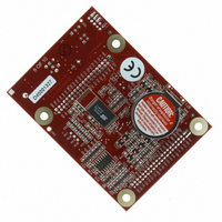
20-101-0356 Rabbit Semiconductor, 20-101-0356 Datasheet - Page 27

20-101-0356
Manufacturer Part Number
20-101-0356
Description
COMPUTER SINGLE-BOARD BL1800
Manufacturer
Rabbit Semiconductor
Datasheet
1.20-101-0356.pdf
(94 pages)
Specifications of 20-101-0356
Module/board Type
Single Board Computer Module
Product
Modules
Data Bus Width
8 bit
Processor Type
Rabbit 2000
Sram
128 KB
Flash
256 KB
Timers
8 bit, 10 bit
Number Of I/os
14
Backup Battery
3 V Lithium Coin Type
Operating Voltage
8 V to 40 V
Power Consumption
1.2 W
Board Size
89 mm x 64 mm x 19 mm
Description/function
Computer Module
For Use With/related Products
BL1800
Lead Free Status / RoHS Status
Lead free / RoHS Compliant
Other names
316-1079
3.4 D/A Converters
Two digital-to-analog (D/A) converter outputs, DA0 and DA1, are supplied on the Jack-
rabbit. These are shown in Figure 10.
The D/A converters have no reference voltage. Although they may be fairly accurate from
one programmed voltage to the next, they do not have absolute accuracy. This is because
Vcc can change ±5%, the PWM outputs might not achieve the full 0 V and 5 V rail out of
the processor, and the gain resistors in the circuit have a 1% tolerance. The D/A converters
therefore need individual calibration, with the calibration constants held in software
before absolute accuracy can be relied on. The Jackrabbit is sold without such calibration.
Note that DA0 is used to provide a reference voltage for the A/D converter and is unavail-
able for D/A conversion when the A/D converter is being used.
Pulse-width modulation (PWM) is used for the D/A conversion. This means that the digi-
tal signal, which is either 0 V or 5 V, is a train of pulses. This means that if the signal is
taken to be usually at 0 V (or ground), there will be 5 V pulses. The voltage will be 0 V for
a given time, then jump to 5 V for a given time, then back to ground for a given time, then
back to 5 V, and so on. A hardware filter in the circuit consisting of a resistor and capacitor
averages the 5 V signal and the 0 V signal over time. Therefore, if the time that the signal
is at 5 V is equal to the time the signal is 0 V, the duty cycle will be 50%, and the average
signal will be 2.5 V. If the time at 5 V is only 25% of the time, then the average voltage
will be 1.25 V. Thus, the software needs to only vary the time the signal is at 5 V with
respect to the time the signal is at 0 V to achieve any desired voltage between 0 V and 5 V.
User’s Manual
Figure 10. Schematic Diagram of D/A Converters
W
W
W
W
W
W
W
W
W
23


