20-101-0356 Rabbit Semiconductor, 20-101-0356 Datasheet - Page 56
20-101-0356
Manufacturer Part Number
20-101-0356
Description
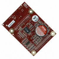
COMPUTER SINGLE-BOARD BL1800
Manufacturer
Rabbit Semiconductor
Datasheet
1.20-101-0356.pdf
(94 pages)
Specifications of 20-101-0356
Module/board Type
Single Board Computer Module
Product
Modules
Data Bus Width
8 bit
Processor Type
Rabbit 2000
Sram
128 KB
Flash
256 KB
Timers
8 bit, 10 bit
Number Of I/os
14
Backup Battery
3 V Lithium Coin Type
Operating Voltage
8 V to 40 V
Power Consumption
1.2 W
Board Size
89 mm x 64 mm x 19 mm
Description/function
Computer Module
For Use With/related Products
BL1800
Lead Free Status / RoHS Status
Lead free / RoHS Compliant
Other names
316-1079


4.4.1.3 Analog Output
The two analog output channels on the Jackrabbit (DA0 and DA1 on header J5) are con-
trolled by a pulse-width modulation (PWM) driver. This requires the use of some fraction
of the CPU cycles when the driver is running (up to 20% when both D/A channels are
used). A voltage is selected by giving a value from 0 to 1024 to the driver, corresponding
roughly to 0.1 V to 3.5 V on DA0. Because of the PWM interrupt frequency, the PWM
driver can provide a continuous range of voltage output in the range from 0.1 V to 3.0 V
for DA0, and 0.6 V to 3.6 V for DA1. These ranges can be specified with the constants
PWM_MIN
PWM_MIN
ting DA1 to
ues below
for DA1) will be rounded up to 1024.
The output channels can also be set in an “always on” or “always off” mode, which does
not require CPU cycles. The “always on” mode is set by requesting an output value of
1024, and will provide about 3.4 V on channel DA0, and 3.6 V on DA1. The “always off”
mode is selected by asking for a value of 0, and provides an output of around 0.1 V on
DA0 and 0.0 V on DA1.
See Table 5 for a summary of the possible analog output voltages corresponding to values
given in the
52
void digOut(int channel, int value);
void digOn(int channel);
void digOff(int channel);
sets the state of a digital output bit.
sets the state of a digital output bit to on (1).
sets the state of a digital output bit to off (0).
jrioInit
channel
value
jrioInit
channel
jrioInit
channel
NOTE: See the sample program JRIOTEST.C for an example of using the digital out-
,
put functions.
will output 0.1 V, and setting it to
PWM_MIN
PWM_MAX0
is the output value (0 or 1).
anaOut
PWM_MIN
is the output channel number (0-3 on the Jackrabbit).
is the output channel number (0–3 on the Jackrabbit).
is the output channel number (0–3 on the Jackrabbit).
must be called first.
must be called first.
must be called first.
will be rounded down to 0, and values above
function.
, and
will output 0.6 V, and setting it to
PWM_MAX1
. In other words, setting channel DA0 to the value
PWM_MAX0
will output 3.0 V. Similarly, set-
PWM_MAX1
PWM_MAX0
will output 3.6 V. Val-
Jackrabbit (BL1800)
(
PWM_MAX1
Related parts for 20-101-0356
Image
Part Number
Description
Manufacturer
Datasheet
Request
R

Part Number:
Description:
COMPUTER SGL-BRD BL2500 29.4MHZ
Manufacturer:
Rabbit Semiconductor
Datasheet:

Part Number:
Description:
COMPUTER SGL-BRD BL2500 29.4MHZ
Manufacturer:
Rabbit Semiconductor
Datasheet:

Part Number:
Description:
DISPLAY GRAPHIC 12KEY PROG OP670
Manufacturer:
Rabbit Semiconductor
Datasheet:
Part Number:
Description:
DISPLAY GRAPHIC 12KEY ETH OP6700
Manufacturer:
Rabbit Semiconductor
Datasheet:

Part Number:
Description:
COMPUTER SINGLE-BOARD BL2030
Manufacturer:
Rabbit Semiconductor
Part Number:
Description:
COMPUTER SGL-BOARD ETH BL2010
Manufacturer:
Rabbit Semiconductor

Part Number:
Description:
MODULE OP6810 W/O ETH/MEM EXPANS
Manufacturer:
Rabbit Semiconductor
Datasheet:
Part Number:
Description:
COMPUTER SINGLE-BOARD BL2020
Manufacturer:
Rabbit Semiconductor
Part Number:
Description:
COMPUTER BL2010 W/FRICTION LOCK
Manufacturer:
Rabbit Semiconductor
Part Number:
Description:
COMPUTER BL2020 W/FRICTION LOCK
Manufacturer:
Rabbit Semiconductor
Part Number:
Description:
COMPUTER SGL-BRD BL2500 44.2MHZ
Manufacturer:
Rabbit Semiconductor
Datasheet:
Part Number:
Description:
COMPUTER SGL-BOARD FULL BL2000
Manufacturer:
Rabbit Semiconductor

Part Number:
Description:
COMPUTER SINGLE-BOARD BL2110
Manufacturer:
Rabbit Semiconductor

Part Number:
Description:
COMPUTER SGL-BRD 29.4MHZ BL2610
Manufacturer:
Rabbit Semiconductor
Datasheet:
Part Number:
Description:
INTERFACE OP6800 512K FLASH&SRAM
Manufacturer:
Rabbit Semiconductor
Datasheet: