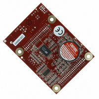
20-101-0356 Rabbit Semiconductor, 20-101-0356 Datasheet - Page 59

20-101-0356
Manufacturer Part Number
20-101-0356
Description
COMPUTER SINGLE-BOARD BL1800
Manufacturer
Rabbit Semiconductor
Datasheet
1.20-101-0356.pdf
(94 pages)
Specifications of 20-101-0356
Module/board Type
Single Board Computer Module
Product
Modules
Data Bus Width
8 bit
Processor Type
Rabbit 2000
Sram
128 KB
Flash
256 KB
Timers
8 bit, 10 bit
Number Of I/os
14
Backup Battery
3 V Lithium Coin Type
Operating Voltage
8 V to 40 V
Power Consumption
1.2 W
Board Size
89 mm x 64 mm x 19 mm
Description/function
Computer Module
For Use With/related Products
BL1800
Lead Free Status / RoHS Status
Lead free / RoHS Compliant
Other names
316-1079
4.4.2 Serial Communication Drivers
Library files included with Dynamic C provide a full range of serial communications sup-
port. The
PACKET.LIB
ited by the 9th bit, by transmission gaps, or with user-defined special characters. Both
libraries provide blocking functions, which do not return until they are finished transmit-
ting or receiving, and nonblocking functions, which must be called repeatedly until they
are finished. For more information, see the Dynamic C Function Reference Manual and
Technical Note 213, Rabbit Serial Port Software.
4.4.2.1 RS-485 Serial Communication Drivers
The
drivers for use with the Jackrabbit. These drivers are used with the drivers for Serial Port D
in the
are connected to pin 4 and pin 1 of the SP483EN RS-485 chip at U6. This chip is half
duplex, requiring pin 3 (Data Enable) to be high for pins 6 and 7 to act as outputs, and low
for those pins to act as inputs.
Parallel Ports D and E on the Rabbit 2000 are double-buffered to provide precisely timed
updating of the output pins. Each port is divided into an upper and a lower nibble. All bits
of each nibble must be updated simultaneously. Each nibble may be updated constantly at
a rate of
The bits used to select the update rate for each nibble are left random at power-up. If a mode
other than
writing to the port’s data register. In particular, PD5, the RS-485 transmitter control, will not
set the RS-485 transmitter enable unless the upper nibble of Port D is configured properly.
The
clocking features associated with the high nibble of Port D. This effectively disables
digital-to-analog (D/A) converter output channel DA1, the low-resolution D/A converter
channel, which also uses PD4. Channel DA0 has its PWM output clocked separately with
the low nibble, and so is not affected. Because the analog-to-digital converter uses D/A
channel DA0, analog-to-digital conversion is not affected.
There are three RS-485 serial drivers.
User’s Manual
void Jr485Init();
void Jr485Tx();
void Jr485Rx();
Sets up parallel port D pins for RS-485 use.
Sets pin 3 (DE) of the SP483EN chip high to disable Rx and enable Tx.
Resets pin 3 (DE) of the SP483EN chip low to disable Tx and enable Rx.
JR485.LIB
JR485Init
RS232.LIB
perclk
RS232.LIB
perclk
library provides packet-based serial functions where packets can be delim-
/2 or on a match of a selected timer (Timer A1, B1, or B2).
library in the Dynamic C
function in Dynamic C release 6.16 has provision to disable the special
/2 is selected, the bits of a particular port will not update on a simple
library because
library provides a set of circular-buffer-based serial functions. The
serDopen
LIB/JRABLIB
uses PC0 (TXD) and PC1 (RXD), which
directory contains three RS-485
55


