CYP15G0401RB-BGXC Cypress Semiconductor Corp, CYP15G0401RB-BGXC Datasheet
CYP15G0401RB-BGXC
Specifications of CYP15G0401RB-BGXC
Available stocks


Related parts for CYP15G0401RB-BGXC

CYP15G0401RB-BGXC Summary of contents
Page 1
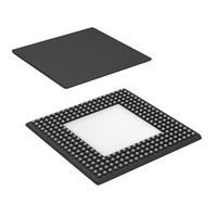
... BGA • Pb free package available • 0.25µ BiCMOS technology Functional Description The CYP15G0401RB Quad HOTLink II™ Receiver is a point-to-point or point-to-multipoint communications building block allowing the transfer of data over high-speed serial links (optical fiber, balanced, and unbalanced copper transmission lines) at signaling speeds ranging from 195-to-1500 MBaud per serial link ...
Page 2
... CYP15G0401RB extends the HOTLink family with enhanced levels of integration and faster data rates, while maintaining serial-link compatibility (data, command, and BIST) with other HOTLink devices. The receivers (RX) of the CYP15G0401RB Quad HOTLink II consist of four byte-wide channels. Each channel accepts a serial bit-stream from one of two ...
Page 3
... CYP15G0401RB Receiver Logic Block Diagram x11 Elasticity Buffer Decoder 8B/10B Framer Deserializer RX Document #: 38-02111 Rev. ** PRELIMINARY x11 x11 Elasticity Elasticity Elasticity Buffer Buffer Buffer Decoder Decoder Decoder 8B/10B 8B/10B 8B/10B Framer Framer Framer Deserializer Deserializer Deserializer RX RX CYP15G0401RB x11 RX Page [+] Feedback ...
Page 4
... TRGCLK– TRGRATE Clock Multiplier SPDSEL Character-Rate Clock Clock ÷2 Select Clock ÷2 Select Clock ÷2 Select Clock ÷2 Select BIST Enable Latch CYP15G0401RB = Internal Signal TRSTZ TMS JTAG TCLK Boundary Scan TDI Controller TDO LFIA 8 RXDA[7:0] RXOPA 3 RXSTA[2:0] RXCLKA+ RXCLKA– ...
Page 5
... OPD CLK- RXSTD GND RXSTD N/C TRG N/C GND [0] [2] CLK+ RXSTD GND N/C GND GND GND GND [1] RXDD GND N/C N/C GND N/C GND [0] CYP15G0401RB INA2- N/C V INB1- N/C INB2- N/C CC INA2+ N/C V INB1+ N/C INB2+ N/C CC N/C GND V TRG ...
Page 6
... CLK- D [1] GND N/C TRG N/C RXSTD GND RXSTD CLK+ [2] [0] GND GND GND GND N/C GND RXSTD [1] GND N/C GND N/C N/C GND RXDD [0] CYP15G0401RB IND1- V N/C INC2- N/C INC1- CC IND1+ V N/C INC2+ N/C INC1 PAR V INSELB INSELC TMS TDI C ...
Page 7
... Pin Descriptions CYP15G0401RB Quad HOTLink II Receiver Pin Name I/O Characteristics Receive Path Data Signals RXDA[7:0] LVTTL Output, Parallel Data Output. These outputs change following the rising edge of the selected RXDB[7:0] synchronous to the receive interface clock. RXDC[7:0] selected RXCLKx↑ output When the Decoder is enabled (DECMODE = HIGH or MID), these outputs represent ...
Page 8
... Pin Descriptions (continued) CYP15G0401RB Quad HOTLink II Receiver Pin Name I/O Characteristics RXCLKA± Three-state, LVTTL Receive Character Clock Output or Clock Select Input. When configured such that all RXCLKB± Output clock or static output data paths are clocked by the recovered clock (RXCKSEL = MID), these true and RXCLKC± ...
Page 9
... Pin Descriptions (continued) CYP15G0401RB Quad HOTLink II Receiver Pin Name I/O Characteristics Device Control Signals [3] PARCTL Three-level Select , Parity Generate Control. Used to control the different parity generate functions. When static control input LOW, parity checking is disabled, and the RXOPx outputs are all disabled (High-Z). When MID, and the 10B/8B Decoder is enabled (DECMODE ≠ ...
Page 10
... CC GND Signal and power ground for all internal circuits. CYP15G0401RB HOTLink II Operation The CYP15G0401RB is a highly configurable device designed to support reliable transfer of large quantities of data, using high-speed serial links, from one or multiple sources to one destination. This device supports four single-byte or single-character channels. ...
Page 11
... LFIx should be HIGH. Receive Channel Enabled The CYP15G0401RB contains four receive channels that can be independently enabled and disabled. Each channel can be enabled or disabled separately through the BRE[3:0] inputs, as controlled by the RXLE latch-enable signal. When RXLE is ...
Page 12
... The location of this character in the data stream is used to determine the character boundaries of all following characters. Framing Character The CYP15G0401RB allows selection of two combinations of framing characters to support requirements of different inter- faces. The selection of the framing character is made through the FRAMCHAR input. ...
Page 13
... Code rule violations or running disparity errors that occur as part of the BIST loop do not cause an error indication. RXSTx[2:0] indicates 010b or 100b for one character period per BIST loop to indicate loop completion. This status can be used to check test pattern progress. These same status values CYP15G0401RB Page [+] Feedback ...
Page 14
... Power Control The CYP15G0401RB supports user control of the powered up or down state of each receive channel. The receive channels are controlled by the RXLE signal and the values present on the BRE[3:0] bus. Powering down unused channels will save power and reduce system heat generation. Controlling system power dissipation will improve the system performance ...
Page 15
... Device Reset State When the CYP15G0401RB is reset by assertion of TRSTZ, the Receive Enable Latches are both cleared, and the BIST Enable Latch is preset. In this state, all receive channels are disabled, and BIST is disabled on all channels. ...
Page 16
... Parity Generation In addition to the eleven data and status bits that are presented by each channel, an RXOPx parity output is also available on each channel. This allows the CYP15G0401RB to support ODD parity generation for each channel. To handle a wide range of system environments, the CYP15G0401RB supports different forms of parity generation, including no parity. ...
Page 17
... BIST Error. While comparing characters, a mismatch was found in one or more of the decoded character bits. 111 3 BIST Wait. The receiver is comparing characters. but has not yet found the start of BIST character to enable the LFSR. Document #: 38-02111 Rev. ** PRELIMINARY Status Receive BIST Status (Receive BIST = Enabled) CYP15G0401RB Page [+] Feedback ...
Page 18
... When interfacing to transmitter only HOTLink II devices such as the CYP15G0401TB it is necessary to have RXCKSEL = MID. JTAG Support The CYP15G0401RB contains a JTAG port to allow system level diagnosis of device interconnect. Of the available JTAG modes, only boundary scan is supported. This capability is present only on the LVTTL inputs, LVTTL outputs and the TRGCLK± ...
Page 19
... BIST_START (101) Elasticity Buffer Error Yes No Compare Next Character BIST_COMMAND_COMPARE (001) Match Command Data or Command Data End-of-BIST State Yes, RXSTx = BIST_LAST_GOOD (010) No, RXSTx = Figure 2. Receive BIST State Machine CYP15G0401RB Receive BIST Detected LOW RX PLL Out of Lock RXSTx = RXSTx = BIST_DATA_COMPARE (000) No Page [+] Feedback ...
Page 20
... Document #: 38-02111 Rev. ** PRELIMINARY Static Discharge Voltage........................................... > 2000V (per MIL-STD-883, Method 3015) Latch-up Current..................................................... > 200 mA Power-up Requirements The CYP15G0401RB requires one power-supply. The voltage on any input or I/O pin cannot exceed the power pin during power-up Operating Range + 0.5V CC Range ...
Page 21
... V = 1.4V th 0.8V 0.8V GND ≤ (b) LVTTL Input Test Waveform CYP15G0401RB AC Characteristics Parameter CYP15G0401RB Receiver LVTTL Switching Characteristics Over the Operating Range f RXCLKx Clock Output Frequency RS t RXCLKx Period RXCLKP t RXCLKx HIGH Time (RXRATE = LOW) RXCLKH RXCLKx HIGH Time (RXRATE = HIGH) t ...
Page 22
... Received Data Valid Time from RXCLKC (RXCKSEL = LOW) TRGCDV+ [4] t TRGCLK Frequency Referenced to Received Clock Period TRGRX CYP15G0401RB Receive Serial Inputs and CDR PLL Characteristics Over the Operating Range t Receive PLL lock to input data stream (cold start) RXLOCK Receive PLL lock to input data stream t ...
Page 23
... Switching Waveforms for the CYP15G0401RB HOTLink II Receiver Receive Interface Read Timing RXCKSEL = LOW TRGRATE = LOW TRGCLK RXDx[7:0], RXSTx[2:0], RXOPx RXCLKA RXCLKC Receive Interface Read Timing RXCKSEL = LOW TRGRATE = HIGH TRGCLK RXDx[7:0], RXSTx[2:0], RXOPx RXCLKA RXCLKC Receive Interface Read Timing RXCKSEL = HIGH or MID ...
Page 24
... Switching Waveforms for the CYP15G0401RB HOTLink II Receiver Receive Interface Read Timing RXCKSEL = HIGH or MID RXRATE = HIGH RXCLKx+ – RXCLKx RXDx[7:0], RXSTx[2:0], RXOPx Document #: 38-02111 Rev. ** PRELIMINARY (continued) t RXCLKP t RXCLKH t RXDV– t RXDV+ CYP15G0401RB t RXCLKL Page [+] Feedback ...
Page 25
... N/C NO CONNECT E01 VCC POWER E02 VCC POWER E03 VCC POWER E04 VCC POWER E17 VCC POWER E18 VCC POWER CYP15G0401RB Ball ID Signal Name Signal Type E19 VCC POWER E20 VCC POWER F01 N/C NO CONNECT F02 VCC POWER F03 VCC POWER ...
Page 26
... GND GROUND V15 VCC POWER V16 VCC POWER V17 RXDA[7] LVTTL OUT V18 RXDA[3] LVTTL OUT V19 RXDA[0] LVTTL OUT CYP15G0401RB Ball ID Signal Name Signal Type V20 RXSTA[0] LVTTL OUT W01 VCC POWER W02 VCC POWER W03 LFID LVTTL OUT W04 RXCLKD– ...
Page 27
... After powering on, the Transmitter may assume either a positive or negative value for its initial running disparity. Upon transmission of any Transmission Character, the transmitter will select the proper version of the Transmission Character based on the current running disparity value, and the Trans- CYP15G0401RB the validity of received ...
Page 28
... Transmission Character in which the error occurred. Table 12 shows an example of this behavior. Character RD Character D21.1 – D10.2 101010 1001 – 010101 0101 101010 1011 + 010101 0101 D21.0 + D10.2 CYP15G0401RB Data OUT 765 43210 Hex Value 000 00000 00 000 00001 01 000 00010 02 ...
Page 29
... D28.1 001 11100 010001 1011 D29.1 001 11101 100001 1011 D30.1 001 11110 010100 1011 D31.1 001 11111 CYP15G0401RB Current RD− Current RD+ abcdei fghj abcdei fghj 100111 1001 011000 1001 011101 1001 100010 1001 101101 1001 010010 1001 110001 1001 ...
Page 30
... D29.3 011 11101 100001 0101 D30.3 011 11110 010100 0101 D31.3 011 11111 011000 1101 D0.5 101 00000 CYP15G0401RB Current RD− Current RD+ abcdei fghj abcdei fghj 100111 0011 011000 1100 011101 0011 100010 1100 101101 0011 010010 1100 110001 1100 ...
Page 31
... D28.5 101 11100 010001 1101 D29.5 101 11101 100001 1101 D30.5 101 11110 010100 1101 D31.5 101 11111 CYP15G0401RB Current RD− Current RD+ abcdei fghj abcdei fghj 011101 1010 100010 1010 101101 1010 010010 1010 110001 1010 110001 1010 110101 1010 ...
Page 32
... D28.7 111 11100 010001 0110 D29.7 111 11101 100001 0110 D30.7 111 11110 010100 0110 D31.7 111 11111 CYP15G0401RB Current RD− Current RD+ abcdei fghj abcdei fghj 100111 0001 011000 1110 011101 0001 100010 1110 101101 0001 010010 1110 110001 1110 ...
Page 33
... C1.7 (CE1) 111 00001 [43] C2.7 (CE2) 111 00010 [43] C4.7 (CE4) 111 00100 CYP15G0401RB Current RD− Current RD+ abcdei fghj abcdei fghj 001111 0100 110000 1011 001111 1001 110000 0110 001111 0101 110000 1010 001111 0011 110000 1100 001111 0010 ...
Page 34
... Ordering Information Speed Ordering Code Standard CYP15G0401RB-BGC Standard CYP15G0401RB-BGI Standard CYP15G0401RB-BGXC Standard CYP15G0401RB-BGXI Package Diagram 256-Lead L2 Ball Grid Array ( 1.57 mm) BL256 TOP VIEW 27.00±0.13 A1 CORNER I.D. 1.57±0.175 0.97 REF. 0.60±0.10 C SEATING PLANE SIDE VIEW HOTLink is a registered trademark, and HOTLink II, and MultiFrame are trademarks, of Cypress Semiconductor. IBM and ESCON are registered trademarks, and FICON is a trademark, of International Business Machines ...
Page 35
... Document History Page Document Title: CYP15G0401RB Quad HOTLink II™ Receiver Document Number: 38-02111 ECN Issue Orig. of REV. No. Date Change ** 318023 See ECN REV Document #: 38-02111 Rev. ** PRELIMINARY Description of Change New Data Sheet CYP15G0401RB Page [+] Feedback ...