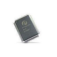
PI7C8140AMAE Pericom Semiconductor, PI7C8140AMAE Datasheet - Page 33

PI7C8140AMAE
Manufacturer Part Number
PI7C8140AMAE
Description
IC PCI-PCI BRIDGE 2PORT 128-QFP
Manufacturer
Pericom Semiconductor
Datasheet
1.PI7C8140AMAE.pdf
(82 pages)
Specifications of PI7C8140AMAE
Applications
*
Interface
*
Voltage - Supply
*
Package / Case
128-QFP
Mounting Type
Surface Mount
Maximum Operating Temperature
+ 85 C
Minimum Operating Temperature
0 C
Mounting Style
SMD/SMT
Operating Supply Voltage
3 V to 3.6 V
Supply Current (max)
230 mA
Lead Free Status / RoHS Status
Lead free / RoHS Compliant
Available stocks
Company
Part Number
Manufacturer
Quantity
Price
Company:
Part Number:
PI7C8140AMAE
Manufacturer:
Pericom
Quantity:
135
Company:
Part Number:
PI7C8140AMAE
Manufacturer:
SONY
Quantity:
469
Part Number:
PI7C8140AMAE
Manufacturer:
PERICOM
Quantity:
20 000
07-0067
3
3.1
3.2
ADDRESS DECODING
The bridge uses three address ranges that control I/O and memory transaction forwarding. These
address ranges are defined by base and limit address registers in the configuration space. This chapter
describes these address ranges, as well as ISA-mode and VGA-addressing support.
ADDRESS RANGES
The bridge uses the following address ranges that determine which I/O and memory transactions are
forwarded from the primary PCI bus to the secondary PCI bus, and from the secondary bus to the
primary bus:
Transactions falling within these ranges are forwarded downstream from the primary PCI bus to the
secondary PCI bus. Transactions falling outside these ranges are forwarded upstream from the
secondary PCI bus to the primary PCI bus.
No address translation is required in the bridge. The addresses that are not marked for downstream are
always forwarded upstream.
I/O ADDRESS DECODING
The bridge uses the following mechanisms that are defined in the configuration space to specify the I/O
address space for downstream and upstream forwarding:
This section provides information on the I/O address registers and ISA mode. Section 3.4 provides
information on the VGA modes.
To enable downstream forwarding of I/O transactions, the I/O enable bit must be set in the command
register in configuration space. All I/O transactions initiated on the primary bus will be ignored if the
I/O enable bit is not set. To enable upstream forwarding of I/O transactions, the master enable bit must
be set in the command register. If the master-enable bit is not set, the bridge ignores all I/O and memory
transactions initiated on the secondary bus.
The master-enable bit also allows upstream forwarding of memory transactions if it is set.
CAUTION
If any configuration state affecting I/O transaction forwarding is changed by a configuration write
operation on the primary bus at the same time that I/O transactions are ongoing on the secondary bus,
Two 32-bit I/O address ranges
Two 32-bit memory-mapped I/O (non-prefetchable memory) ranges
Two 32-bit prefetchable memory address ranges
I/O base and limit address registers
The ISA enable bit
The VGA mode bit
The VGA snoop bit
Page 33 of 82
2-PORT PCI-TO-PCI BRIDGE
March 20, 2007 – Revision 1.01
PI7C8140A


