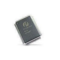
PI7C8140AMAE Pericom Semiconductor, PI7C8140AMAE Datasheet - Page 41

PI7C8140AMAE
Manufacturer Part Number
PI7C8140AMAE
Description
IC PCI-PCI BRIDGE 2PORT 128-QFP
Manufacturer
Pericom Semiconductor
Datasheet
1.PI7C8140AMAE.pdf
(82 pages)
Specifications of PI7C8140AMAE
Applications
*
Interface
*
Voltage - Supply
*
Package / Case
128-QFP
Mounting Type
Surface Mount
Maximum Operating Temperature
+ 85 C
Minimum Operating Temperature
0 C
Mounting Style
SMD/SMT
Operating Supply Voltage
3 V to 3.6 V
Supply Current (max)
230 mA
Lead Free Status / RoHS Status
Lead free / RoHS Compliant
Available stocks
Company
Part Number
Manufacturer
Quantity
Price
Company:
Part Number:
PI7C8140AMAE
Manufacturer:
Pericom
Quantity:
135
Company:
Part Number:
PI7C8140AMAE
Manufacturer:
SONY
Quantity:
469
Part Number:
PI7C8140AMAE
Manufacturer:
PERICOM
Quantity:
20 000
07-0067
4.4
5
5.1
DATA SYNCHRONIZATION
Data synchronization refers to the relationship between interrupt signaling and data delivery. The PCI
Local Bus Specification, Revision 2.2, provides the following alternative methods for synchronizing
data and interrupts:
The bridge does not have a hardware mechanism to guarantee data synchronization for posted write
transactions. Therefore, all posted write transactions must be followed by a read operation, either from
the device to the location just written (or some other location along the same path), or from the device
driver to one of the device registers.
ERROR HANDLING
The bridge checks, forwards, and generates parity on both the primary and secondary interfaces. To
maintain transparency, the bridge always tries to forward the existing parity condition on one bus to the
other bus, along with address and data. The bridge always attempts to be transparent when reporting
errors, but this is not always possible, given the presence of posted data and delayed transactions.
To support error reporting on the PCI bus, the bridge implements the following:
This chapter provides detailed information about how the bridge handles errors. It also describes error
status reporting and error operation disabling.
ADDRESS PARITY ERRORS
The bridge checks address parity for all transactions on both buses, for all address and all bus
commands. When the bridge detects an address parity error on the primary interface, the following
events occur:
The device signaling the interrupt performs a read of the data just written (software).
The device driver performs a read operation to any register in the interrupting device before
accessing data written by the device (software).
System hardware guarantees that write buffers are flushed before interrupts are forwarded.
PERR# and SERR# signals on both the primary and secondary interfaces
Primary status and secondary status registers
The device-specific P_SERR# event disable register
If the parity error response bit is set in the command register, the bridge does not claim the
transaction with P_DEVSEL#; this may allow the transaction to terminate in a master abort. If
parity error response bit is not set, the bridge proceeds normally and accepts the transaction if it
is directed to or across the bridge.
The bridge sets the detected parity error bit in the status register.
The bridge asserts P_SERR# and sets signaled system error bit in the status register, if both the
following conditions are met:
The SERR# enable bit is set in the command register.
The parity error response bit is set in the command register.
Page 41 of 82
2-PORT PCI-TO-PCI BRIDGE
March 20, 2007 – Revision 1.01
PI7C8140A


