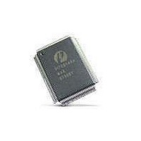
PI7C8140AMAE Pericom Semiconductor, PI7C8140AMAE Datasheet - Page 57

PI7C8140AMAE
Manufacturer Part Number
PI7C8140AMAE
Description
IC PCI-PCI BRIDGE 2PORT 128-QFP
Manufacturer
Pericom Semiconductor
Datasheet
1.PI7C8140AMAE.pdf
(82 pages)
Specifications of PI7C8140AMAE
Applications
*
Interface
*
Voltage - Supply
*
Package / Case
128-QFP
Mounting Type
Surface Mount
Maximum Operating Temperature
+ 85 C
Minimum Operating Temperature
0 C
Mounting Style
SMD/SMT
Operating Supply Voltage
3 V to 3.6 V
Supply Current (max)
230 mA
Lead Free Status / RoHS Status
Lead free / RoHS Compliant
Available stocks
Company
Part Number
Manufacturer
Quantity
Price
Company:
Part Number:
PI7C8140AMAE
Manufacturer:
Pericom
Quantity:
135
Company:
Part Number:
PI7C8140AMAE
Manufacturer:
SONY
Quantity:
469
Part Number:
PI7C8140AMAE
Manufacturer:
PERICOM
Quantity:
20 000
07-0067
12.2 ABNORMAL TERMINATION (INITIATED BY BRIDGE
12.2.1 MASTER ABORT
12.2.2 PARITY AND ERROR REPORTING
12.2.3 REPORTING PARITY ERRORS
MASTER)
Master abort indicates that when the bridge acts as a master and receives no response (i.e., no target
asserts DEVSEL# or S_DEVSEL#) from a target, the bridge de-asserts FRAME# and then deasserts
IRDY#.
Parity must be checked for all addresses and write data. Parity is defined on the P_PAR, and S_PAR
signals. Parity should be even (i.e. an even number of‘1’s) across AD, CBE, and PAR. Parity
information on PAR is valid the cycle after AD and CBE are valid. For reads, even parity must be
generated using the initiators CBE signals combined with the read data. Again, the PAR signal
corresponds to read data from the previous data phase cycle.
For all address phases, if a parity error is detected, the error should be reported on the P_SERR# signal
by asserting P_SERR# for one cycle and then 3-stating two cycles after the bad address. P_SERR# can
only be asserted if bit 6 and 8 in the Command Register are both set to 1. For write data phases, a parity
error should be reported by asserting the P_PERR_L signal two cycles after the data phase and should
remain asserted for one cycle when bit 6 in the Command register is set to a 1. The target reports any
type of data parity errors during write cycles, while the master reports data parity errors during read
cycles.
Detection of an address parity error will cause the PCI-to-PCI Bridge target to not claim the bus
(P_DEVSEL# remains inactive) and the cycle will then terminate with a Master Abort. When the bridge
Initiator
Master on Primary
Master on Primary
Master on Secondary
Master on Secondary
Master on Secondary
Target
Target on Secondary
Target not on Primary nor
Secondary Port
Target on the same
Secondary Port
Target on Primary or the
other Secondary Port
Target not on Primary nor
the other Secondary Port
Page 57 of 82
Response
normally if it is able to be posted, otherwise return
with a retry. It then passes the cycle to the appropriate
port. When the cycle is complete on the target port, it
will wait for the initiator to repeat the same cycle and
end with normal termination.
Bridge does not respond and the cycle will terminate
as master abort.
Bridge does not respond.
Bridge asserts S_DEVSEL#, terminates the cycle
normally if it is able to be posted, otherwise returns
with a retry. It then passes the cycle to the appropriate
port. When cycle is complete on the target port, it will
wait for the initiator to repeat the same cycle and end
with normal termination.
Bridge does not respond.
Bridge asserts P_DEVSEL#, terminates the cycle
2-PORT PCI-TO-PCI BRIDGE
March 20, 2007 – Revision 1.01
PI7C8140A


