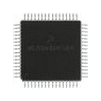
MC68HC908LD60IFU Freescale Semiconductor, MC68HC908LD60IFU Datasheet - Page 187

MC68HC908LD60IFU
Manufacturer Part Number
MC68HC908LD60IFU
Description
Manufacturer
Freescale Semiconductor
Datasheet
1.MC68HC908LD60IFU.pdf
(292 pages)
Specifications of MC68HC908LD60IFU
Cpu Family
HC08
Device Core Size
8b
Frequency (max)
6MHz
Program Memory Type
Flash
Program Memory Size
60KB
Total Internal Ram Size
1KB
# I/os (max)
39
Number Of Timers - General Purpose
2
Operating Supply Voltage (typ)
3.3V
Operating Supply Voltage (max)
3.6V
Operating Supply Voltage (min)
3V
On-chip Adc
6-chx8-bit
Instruction Set Architecture
CISC
Operating Temp Range
0C to 85C
Operating Temperature Classification
Commercial
Mounting
Surface Mount
Pin Count
64
Package Type
PQFP
Lead Free Status / Rohs Status
Compliant
Available stocks
Company
Part Number
Manufacturer
Quantity
Price
- Current page: 187 of 292
- Download datasheet (4Mb)
MC68HC908LD60
Freescale Semiconductor
—
Rev. 1.1
MMAST — Master Control Bit
MMRW — Master Read/Write
MMBR2–MMBR0 — Baud Rate Select
This bit is set to initiate a master mode transfer. In master mode, the
module generates a start condition to the SDA and SCL lines,
followed by sending the calling address stored in MMADR.
When the MMAST bit is cleared by MMNAKIF set (no acknowledge)
or by software, the module generates the stop condition to the lines
after the current byte is transmitted.
If an arbitration loss occurs (MMALIF = 1), the module reverts to slave
mode by clearing MMAST, and releasing SDA and SCL lines
immediately.
This bit is cleared by writing "0" to it or by reset.
This bit will be transmitted out as bit 0 of the calling address when the
module sets the MMAST bit to enter master mode. The MMRW bit
determines the transfer direction of the data bytes that follows. When
it is "1", the module is in master receive mode. When it is "0", the
module is in master transmit mode. Reset clears this bit.
These three bits select one of eight clock rates as the master clock
when the module is in master mode.
Since this master clock is derived the CPU bus clock, the user
program should not execute the WAIT instruction when the MMIIC
module in master mode. This will cause the SDA and SCL lines to
hang, as the WAIT instruction places the MCU in wait mode, with CPU
clock is halted. These bits are cleared upon reset. (See
Baud Rate
1 = Master mode operation
0 = Slave mode operation
1 = Master mode receive
0 = Master mode transmit
Multi-Master IIC Interface (MMIIC)
Select.)
Multi-Master IIC Interface (MMIIC)
Multi-Master IIC Registers
Table 14-2 .
Technical Data
187
Related parts for MC68HC908LD60IFU
Image
Part Number
Description
Manufacturer
Datasheet
Request
R
Part Number:
Description:
Manufacturer:
Freescale Semiconductor, Inc
Datasheet:
Part Number:
Description:
Manufacturer:
Freescale Semiconductor, Inc
Datasheet:
Part Number:
Description:
Manufacturer:
Freescale Semiconductor, Inc
Datasheet:
Part Number:
Description:
Manufacturer:
Freescale Semiconductor, Inc
Datasheet:
Part Number:
Description:
Manufacturer:
Freescale Semiconductor, Inc
Datasheet:
Part Number:
Description:
Manufacturer:
Freescale Semiconductor, Inc
Datasheet:
Part Number:
Description:
Manufacturer:
Freescale Semiconductor, Inc
Datasheet:
Part Number:
Description:
Manufacturer:
Freescale Semiconductor, Inc
Datasheet:
Part Number:
Description:
Manufacturer:
Freescale Semiconductor, Inc
Datasheet:
Part Number:
Description:
Manufacturer:
Freescale Semiconductor, Inc
Datasheet:
Part Number:
Description:
Manufacturer:
Freescale Semiconductor, Inc
Datasheet:
Part Number:
Description:
Manufacturer:
Freescale Semiconductor, Inc
Datasheet:
Part Number:
Description:
Manufacturer:
Freescale Semiconductor, Inc
Datasheet:
Part Number:
Description:
Manufacturer:
Freescale Semiconductor, Inc
Datasheet:
Part Number:
Description:
Manufacturer:
Freescale Semiconductor, Inc
Datasheet:


